IP Flush Master -V2 Board Connectors
From Zenitel Wiki
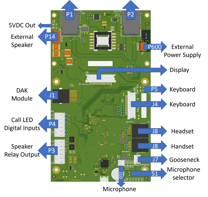
This chapter gives details about connections and indications for:
P1 - LAN port & P2 AUX port
P1:
LAN connector for 10/100 Mbit Ethernet connection. The station can be powered from this connection if the line supports Power over Ethernet (PoE).
The connector has two LEDs in front where the right (R) LED indicates Ethernet speed and the left (L) LED verifies Ethernet link and traffic. (L and R as seen from the connector side)
P2:
RJ45 connector for auxiliary equipment like IP camera, PC or a second IP station. This port does not have an individual IP address. It does not carry power for AUX equipment.
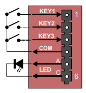
P4 - Inputs and Station LED
6-pin plug-on screw terminal for external connections.
- Pin 1/4 Input 1
- Pin 2/4 Input 2
- Pin 3/4 Input 3
- Pin 5/6 Station LED for call message info.

|
|
J5 - Display
20-pin ZIF connector for LCD display. Separate display panels are available as a kit of 5 units (order no. 1008099000).
J7 - Gooseneck Microphone
3-pin header for connecting gooseneck microphone.
- Pin 1 MIC+
- Pin 2 MIC-
- Pin 3 GND
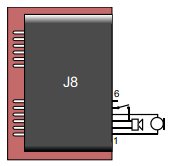
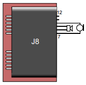
J8 - Handset and Headset
Dual RJ11 for handset and headset. Handset can optionally be connected via J11, J12 and J13.
Handset:
- Pin 1 Mic+
- Pin 2 Spk+
- Pin 3 Spk- (0 V)
- Pin 4 Mic-
- Pin 5 Hook-switch (must be connected to pin 6 via a switch)
- Pin 6 Hook-switch Ground
Headset:
- Pin 7 Mic+
- Pin 8 Spk+
- Pin 9 Spk-
- Pin 10 Mic-
- Pin 11 PTT Ground
- Pin 12 PTT (Not currently supported by SW)
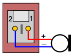
J10 - Microphone
Internal microphone
- Pin 1 MIC+
- Pin 2 MIC-
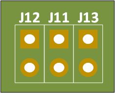
J11, J12 & J13 - Handset
Pin header for handset connection. Same as J8 pin 1 - 6.
- J11 Pin 1 Spk+
- J11 Pin 2 Spk-
- J12 Pin 1 Mic+
- J12 Pin 2 Mic-
- J13 Pin 1 OFFHOOK
- J13 Pin 2 GND
S1 - Microphone Selection
Slide-switch to select internal microphone (Int) or gooseneck microphone (Ext).


