CRM III - Control Room Master
From Zenitel Wiki
Introduction
About This Manual
This manual provides the following information about the Control Room Master (CRM-III) from Stentofon:
- A functional description outlining the capabilities of the station
- An installation and commissioning guide explaining how to install the station as well as elementary programming of the station and the exchange
- A user guide summarizing how to use the function
The item numbers for the CRM-III stations are:
- With gooseneck microphone: 100 7004 000
- With electret microphone: 100 7003 000
Reader Group
•:* The functional description is intended for salespeople and consultants.
- The installation and commissioning guide is written for installation personnel with a technical background, who are familiar with the functionality and programming of the relevant Stentofon exchange (TouchLine or AlphaCom).
- The quick reference guide is intended for all users and operators of the Control Room Master. There is one section for TouchLine users, and another for AlphaCom users.
Related Documentation
| Data Sheet "Control Room Master III - Model 7003" | A100K10185 |
|---|---|
| Manual "Control Handler System - Commissioning / User guide" | A100K10174 |
| AlphaCom Installation and Commissioning manual | A100K10002 |
| System Description, Installation & Commissioning for alphaCom 4/5 - add-on to A100K10001 and A100K10002 | A100K10197 |
Liability
Stentofon AS and its subsidiaries assume no responsibility for any errors that may appear in its documentation, or damages arising from the information in it. No information in this publication should be regarded as a warranty made by Stentofon. This publication may be updated without notice.
Product names mentioned in this publication may be trademarks. They are used only for identification.
Brief Description
This advanced control room master features a large 4 x 20 character alphanumeric display with backlight, full dialing keypad, 8 programmable single-touch keys, answer-next-in-queue key, handset, sensitive electret or gooseneck microphone and a powerful 1W loudspeaker. The station offers full loudspeaking conversation with automatic switching of the speech direction. Manual override of speech direction is also possible.
The station's display provides full information on the current conversation and call queue. The information includes the directory number and name/location. An answer-next-in-queue button allows you to respond to calls according to priority and time of arrival.
The station can be used with either the TouchLine or the AlphaCom exchange.
- The CRM III stations complies with the EMC requirements:
- EN 50081-1 Jan. 92 (emission)
- EN 50082-1 Jan. 92 (Immunity)
Functional Description
Application Areas
The Control Room Master III is intended for applications with a centralized control unit such as security centers for office and industrial buildings - including elevator communications - or prisons.
Possible Configurations
You can use the CRM-III unit with a Stentofon TouchLine exchange or with an AlphaCom exchange.
The CRM-III cannot be used with a TouchLine Compact exchange.
TouchLine Exchange:
- Any size of exchange
- Up to 15 CRM-III units pr DPB (Data Processing Board)
- 4-line configurable display information
AlphaCom Exchange:
- Any size of exchange
- In an AlphaNet installation with software 06.00 the CRM-III only handles Call Requests coming in from the exchange where the CRM-III is connected
- Any number of CRM-III units
- 4-line display information
Features
For a TouchLine exchange, the CRM-III queuing functionality is based on the Control Handler System (CHS) software on the DPB board.
For an AlphaCom exchange, the CRM-III queuing functionality is based on the AlphaCom's internal message feature.
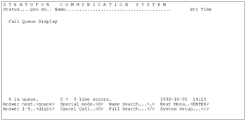
- 4x20 character display with backlight. See page 38 for display information in TouchLine exchange and page 42 for display information in AlphaCom exchanges.
- Multiple call-in annunciation with full display information and different priority levels.
- Call queue size:
- - TouchLine - up to 100 inputs.
- - AlphaCom - up to 1100 inputs.
- Auto acknowledgment to call-in point by flashing station lamp. Voice message acknowledgment requires a Speech Message Board (SMB) in the TouchLine system, or an ASVP board in the AlphaCom system.
- Buzzer indication of queue.
==Single-Touch Keys
- Single touch access to stations, group calls, audio monitoring, public adress zones, radio channels and telephone lines.
Line Monitoring
When Line Monitoring is activated, the system status appears on the CRM-III display.
For the TouchLine system, see the Call Handler documentation for details of how to display line monitoring information. Please note that special PMFR software must be installed (1000 681030).
For the AlphaCom, see the AlphaCom Installation and Commissioning manual.
Microphone
- Model 7003 has an electret microphone with automatic sensitivity adjustment.
- Model 7004 has a goose-neck microphone with a noise-canceling feature.
Installation and Commissioning - TouchLine
Hardware and Software Requirements
- TouchLine exchange with:
- - Subscriber Board ABD-2 (1000 610120)
- - PMFR board(1000 631690)
- - Data Processing Board DPB (1000 638710)with CHS software Version 04.00 or later (1000 683010).
- - Terminal (such as VT100 or VT200) or PC with terminal emulation for programming the DPB board.
- Control Room Master III station (1000 700300/1000 700400)
- Local +12V DC / 300 mA power supply for the station. (If ordering from Stentofon: EQPOW 20490 Mascot Power 6823/6-12)
- Station cable (Hirschmann plug: EPKAB98500; RJ45 modular jack: EPKAB98510).
Optional Extras
The line monitoring feature requires special PMFR software: order no. 1000 681030.
The voice message option for automatic acknowledgment to the call-in point requires a Speech Message Board (SMB, order number 1000 60000) and one free program channel for the message distribution.
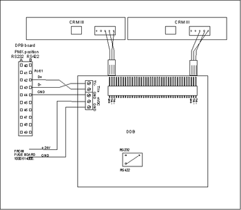
When there are two or more CRM-III stations, the data must be distributed via a separate Data Distribution Board (DDB - order number 1000 638850). Mount the Data Distribution Board to a mounting frame, order number 1000 614000.
Cabling
Data Processing Board
Install the DPB board in the TouchLine exchange as explained in the installation instructions included with the board (TouchLine System Data Processing Board DPB 1000638710 Installation Instructions, IM 1569).
CRM-III
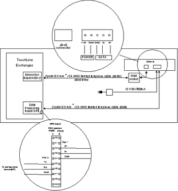
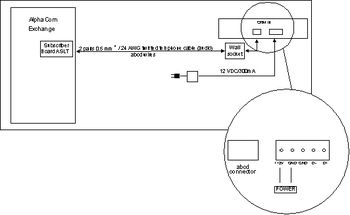
Connect the CRM-III station as shown in Figure 3-1.
Audio
Connect the station cable to the station's abcd connector.
There are two alternative station cables:
- 3-meter cable with 6-pin Hirschmann plug.
- Connection:
- a - pin 1
- b - pin 2
- c - pin 4
- d - pin 6
- 3-meter cable with RJ45 modular jack.
- Connection:
- a - pin 3
- b - pin 6
- c - pin 7
- d - pin 8
Data
Connect the cable from DPB Port 1 (pin B42-B44) to the corresponding pins on the station.
With two more CRM-III stations, you need a Data Distribution Board (DDB) for distribution of the data. See Figure Figure 3-2.
The DDB-board has 13 identical outputs.
Power
Connect to the local power supply (12V DC)
The data cable can have a length of up to 1400 meters (4590 feet), or more if heavier wires are used.
Terminal for DPB Programming
Connect the terminal/PC to Port 2 of the DPB board as shown in Figure 3-1.
Enable Data Communication with the station
Set the switches on the station as shown in Section 3.5
Programming the Exchange
This programming instruction covers programming of the PMFR and DPB boards. We have used the following set of directory numbers in the example - other directory numbers can be used:
| CRM-III directory number | 100 |
|---|---|
| Priority 0 Call Request | 6900 |
| Priority 2 Call Request | 6901 |
| Priority 3 Call Request | 6902 |
| Display identification code | 689 |
| Answer next in queue | 6891 |
| Clear next in queue | 6892 |
The example uses the following DPB ports:
| Display data for CRM-III | Port 1 |
|---|---|
| Terminal port on DPB | Port 2 |
Programming the PMFR Board
To program the PMFR board, you use the programming panel
Baud Rate
Set the baud rate to 9600:
| Select the opcode | E54 |
|---|---|
| Read line 18 | 18 + RD |
| Enter the value 0034 in this line, and activate the command | 0034 + ACT |
| Step to line 19 | STP |
| Enter the value 0034 in this line, and activate the command | 0034 + ACT |
| CANCEL |
Press the red reset button on PMFR.
Specify Directory and Call Request Numbers for CRM-III
Each CRM-III station can have up to 4 directory numbers: one directory number for direct calling, and 3 call request numbers for queuing of calls.
It is possible to define different priority levels for the call requests. The priority levels are from 0 to 3, where 3 is highest priority.
Choose a physical position with an ABD-2 subscriber board connection for the CRM-III directory number. (If the CRM-III is already connected, you can press 788 on the station to see its physical number in Display B of the programming panel.)
In the example, the CRM-III has directory number 100:
| Select the opcode | E48 |
|---|---|
| Read line for physical position to be used | <phys. pos.> + RD |
| Enter the value for the directory number in this line, and activate the command | F100 + ACT |
| CANCEL |
Next, program the call request numbers (6900-6902 in this example) for the CRM-III station. You can use any physical positions that are available - no subscriber board is required for these numbers.
| Select the opcode | E48 |
|---|---|
| Read line for 1st physical position to be used | <phys. pos. 1> + RD |
| Enter the value for the directory number in this line, and activate the command | 6900 + ACT |
| Read line for 2nd physical position to be used | <phys. pos. 2> + RD |
| Read line for 3rd physical position to be used | <phys. pos. 3> + RD |
| Enter the value for the directory number in this line, and activate the command | 6902 + ACT |
| CANCEL |
Specify Dummy Numbers for CRM-III Station Functions
In this step you allocate dummy numbers for the following CRM-III features:
- Identify display station (689)
- Answer next in queue (6891)
- Delete queue entry (6892)
| Select the opcode | E51 |
|---|---|
| Find a free line and read it | <free line 1> + RD |
| Enter the value for the dummy number for display identification, and activate | F689 + ACT |
| Find another free line and read it | <free line 2> + RD |
| Enter the value for the dummy number for "Answer next in queue", and activate | 6891 + ACT |
| Find another free line and read it | <free line 3> + RD |
| Enter the value for the dummy number for "delete queue entry", and activate | 6892 + ACT |
| CANCEL |
Enter reference information for these dummy numbers: Setting the D-bit gives a 1-minute time-out, to avoid problems if a non-CRM-III station happens to dial the number by mistake.
| Select the opcode | E52 |
|---|---|
| Read the value for the dummy number for display identification | F689 + RD |
| Set the reference information for display identification | Bits 0-8 and D ON, the rest OFF |
| Activate the command | ACT + CLR |
| Set the reference information for "Answer next in queue" | Bits 0-8 and D ON, the rest OFF |
| Activate the command | ACT + CLR |
| Read the value for the dummy number for "Delete queue entry" | 6892 + RD |
| Set the reference information for "Delete queue entry" | Bits 0-8 and D ON, the rest OFF |
| Activate the command | ACT |
| CANCEL |
Acknowledgment to Call-in point
To enable acknowledgment to call-in point by flashing the LED on the calling station, the following programming is required:
| Action | Press: |
|---|---|
| Select the opcode | Press E54 |
| Go to line 29 | 29 + RD (*1) |
| Enable flashing LED | FF0F |
| Activate the command | ACT + CLR |
| CANCEL |
- *1) This programming is only required if line 29 is FFFF or 0000. If any othe value, just leave it like it is.
DPB Cold Start using the Programming Panel
All the programming of the queue and display system is held on the DPB board.
As you activate each programming command shown below, watch Display B on the programming panel.

As the command runs, Display B shows the "busy" indication bbxx, where xx is the name of the command.

Wait until bbxx disappears before you continue.
If an Exxx code appears in Display B, it may indicate an error. To clear the Exxx code, press ACT. These codes are described in the CHS documentation.
The LEDs on the DPB board also indicate whether the board is busy or ready for programming. The lowest LED flashes when the board is ready for programming, and shows a steady light when the board is busy.
Create a Board Address
For a new DPB, run the following cold start procedure.
WARNING:

If a DPB board has already been programmed, ALL existing information (names and numbers) on the board will be  deleted.
- 1) To set the DPB in programming mode, press the green button quickly. The lowest diode starts flashing (about once per second).
- 2) To give the board its address, use opcode E62:
| Action | Press: |
|---|---|
| Select the opcode | Press E62 |
| Go to adress 0100 | 0100 + READ |
| Enter the value DFB0 in this line, and activate the command | DFB0 + ACT |
Display A in the Programming Panel should change to A300, and display B to 0000. If not, check the cabling between the PMFR and DPB, and check that the baud rate on PMFR is 9600 baud.
Complete the System Cold Start
System Cold Start is performed in address A300, still using opcode E62:
| Action | Press: |
|---|---|
| Erase NVRAM (0196 if additional RAM on DPB) | 0164 + ACT |
| Reset NVRAM directory, create tables (0296 if additional RAM on DPB) | 0264 + ACT |
| Define call queues | 0300 + ACT |
| x=number of terminals (1 in this example) | 03xA + ACT |
| y=number of CRM-III stations | 04yA + ACT |
| Create dynamic system tables | 0500 + ACT |
| Create subscriber tables (Display B will show E702 or similar Exxx code - this is OK here; it shows that xxx subscribers are available) | 0640 + ACT |
| Load screen test | 0701 + ACT |
| Select terminal type x (se table below) | 080x + ACT |
| Complete the cold start | CANCEL |
Press the red RESET button on the DPB to exit programming mode.
x=1 DEC VT2200 (ANSI 3.64)
x=2 DEC VT220 7-bit (national chars)
x=3 DEC VT100 (7-bit)
x=4 Tandberg TDV2215
x=5 Tandberg TDV2220 (ECMA)
x=6 Qume QVT102 or Lear Siegler ADM11
Configuring the DPB
Adressing the DPB
The board must be addressed after a RESET, or if another board has been addressed in the meantime. It is not necessary to be in "green button" (programming) mode.
| Action | Press: |
|---|---|
| Select the opcode | E62 |
| Read line 0 and enter the board's adress | RD + DFB0 |
| Activate | ACT |
Display A in the Programming Panel should change to A000.
Programming the Queue System
- To enter a value in an address, first read the address (type the address and press RD) and then enter a value in this address (type the value and press ACT).
- For example, to enter the value 5000 in address A0C0, type:
- A0C0 + RD + 5000 + ACT.
- To step to the next address line in a table, press STP.
Define Port 1 for the CRM-III, and Port 2 for the terminal:
| Action | Adress+RD | Value+ACT |
|---|---|---|
| Specify CRM-III as device on Port 1 | A0C0 | 5000 |
| Set default baud rate | A0C2 | 0000 |
| Specify terminal as device on Port 2 | A0C4 | 1000 |
| Set default baud rate | A0C6 | 0000 |
| Press CLR |
Define priority levels for call requests.
Priority levels are from 0 to 3, where level 3 is the most urgent.
| Action | Adress+RD | Value+ACT |
|---|---|---|
| Priority 1 for call to busy station number | A010 | 0001 |
| Priority 0 for 1st call request number | A012 | 0000 |
| Priority 3 for 3rd call request number | A016 | 0003 |
| Press CLR |
Specify that the acknowledgment to the call-in point should be a flashing LED on the calling station:
| Action | Adress+RD | Value+ACT |
|---|---|---|
| Ack. to Priority 0 call-in-point | A200 | 0200 |
| Ack. to Priority 1 call-in-point | A202 | 0200 |
| Ack. to Priority 3 call-in-point | A206 | 0200 |
| Press CLR |
Define buzzer behavior for the CRM-III station. For example, 05 indicates 5 seconds between beeps:
| Action | Adress+RD | Value+ACT |
|---|---|---|
| Priority 0 calls - buzz at 5-sec. intervals | A208 | 0305 |
| Priority 1 calls - buzz at 5-sec. intervals | A20A | 0305 |
| Priority 2 calls - buzz at 5-sec. intervals | A20C | 0305 |
| Priority 3 calls - buzz at 5-sec. intervals | A20E | 0301 |
| Duration of buzzer "beep" - 0,5 seconds | A212 | 0500 |
| Press CLR |
Define Control Room Master III station with associated directory numbers (queue 1):
| Action | Adress+RD | Value+ACT |
|---|---|---|
| Display description | A100 | 2106 |
| Directory number, station | A102 | F100 |
| Directory number, priority 0 | A104 | 6900 |
| Directory number, priority 2 | A106 | 6901 |
| Directory number, priority 3 | A108 | 6902 |
| Press CLR |
Define the terminal (queue 2). In this example, the terminal is used only for inserting name texts. It is also possible to use a terminal for displaying queue information.
| Action | Adress+RD | Value+ACT |
|---|---|---|
| Display description | A110 | 1200 |
| Press CLR |
Enter display description:
| Action | Adress+RD | Value+ACT |
|---|---|---|
| Display 1 - CRM-III | ||
| Physical display description | A2B8 | 1414 |
| Connect window | A2BA | 1114 |
| Menu window (xxxx = 4114 if the above mentioned key labels should always be displayed; otherwise xxxx = 000). | A2BE | xxxx |
| Press CLR |
Enter display line layout:
| Action | Adress+RD | Value+ACT |
|---|---|---|
| Subscriber number/name/info | A0B4 | 0120 |
| Press CLR |
Specify the directory numbers for "Identify display station" and for the functions to be programmed on the single-touch keys on the CRM-III station: "Answer next in queue" and "Delete queue entry". Also set a time-out for the CLEAR key, and enable the background text that shows that calls are being transferred to another station.
| Action | Adress+RD | Value+ACT |
|---|---|---|
| Specify the directory number for the function "Answer next in queue". | A020 | 6891 |
| Press CLR |
| Action | Adress+RD | Value+ACT |
|---|---|---|
| Set the time-out for the CLEAR key | A2C4 | 0005 |
| Enable "Transfer" display - background text $8 | A2C8 | 1000 |
| Specify the directory number for "Identify display station", which one dials to restart a display after loss of power. | A2CA | F689 |
| Specify the directory number for the function "Delete queue entry". | A2CC | 6892 |
| Press CLR |
Rerun queue definitions:
| Action | Adress+RD | Value+ACT |
|---|---|---|
| Define call queues: | A300 | 0300 |
| x = number of terminals (1 in the example) | 03xA | |
| y = number of CRM-III stations | 04yA | |
| Press CLR |
Press red reset button on DPB.
Programming of the DPB from the programming panel is now complete.
Other Options You Can Program
See the CHS manual for how to program:
- fixed transfers
- inactivity transfer
- parallel handling
- auto acknowledgment to call-in point by voice message
- automatic connect
- printer features
- error monitoring.
Programming Background Texts and Name List Using the Terminal
Press ESC twice on the terminal to reset the screen. The Stentofon control system screen appears.
To enter the texts for the CRM-III display:
- 1.Press ! to activate System Setup.
- 2.Select menu option 1. Subscriber name and info.
- 3.To use the first line of the display to show the number of calls in the queue, type:
- EF21<ENTER>
- $D:$E $9 in queue<ENTER>
- NB: For correct spacing, insert two spaces before "in queue". The other spaces are single spaces
- 4.To use the first queue line to display a text when transferred, enter in the name list:
- EF31<ENTER>
- $8<ENTER>
- 5.To use the bottom line of the display for key labels when there is no queue, enter in the name list:
- EF33<ENTER>
- Next Clear Talk Canc<ENTER>
- OR: To have a fixed display for the key labels so they are always visible, enter in the name list:
- EF41<ENTER>
- Next Clear Talk Canc<ENTER>
In the same way, enter the number and name of the CRM-III and all the stations that may call the CRM-III, for example:
- 100<ENTER> CRM-III<ENTER>
- 101<ENTER> Guard X<ENTER>
- 123<ENTER> Elevator A<ENTER>
- 437<ENTER> Main Door<ENTER>
- 678<ENTER> Johnson, K<ENTER>
- 845<ENTER> Parking A<ENTER>
This completes the DPB programming.
Further information on background texts
The CHS software looks up background texts in the name list, using a computed directory number EFwl.
The digits are:
| EF | Constant prefix, never used in regular station of function numbers |
|---|---|
| W | window number |
| 2 = Connect window | |
| 3 = Queue window | |
| 4 = Menu window | |
| L | Line number within window, from 1 and up |
The name text of a background can be either fixed text, or a reference to a system counter. The available values are:
| $1 | Number of stations with line errors (abcd wire) |
|---|---|
| $2 | Number of stations with line error (data line) |
| $3 | Number of transferred stations in the system (transferred guards) |
| $4 | Number of stations with program active |
| $8 | Text of current connect modus - "Transfer" in the example (see the options in the CHS documentation) |
| $9 | Number of queued call for this station (own queue length) |
| $A | Year (4 digits) |
| $B | Month |
| $C | Hour |
| $D | Minute |
Commissioning the Stations
Enabling Data Communication
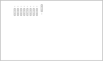
To enable data communication via the separate data line, you need to set the jumpers on the station's Display Driver Board.
- 1. Unscrew the 4 screws fastening the station cabinet.
- 2. Carefully lift both the front and rear panels together to expose the station's Display Driver Board.
- 3. Set the jumpers as shown in the figure to the right:
- 4. Holding the panels together, replace them in their normal position and screw the cabinet together again.
- 5. Now dial 689 to restart the display on the CRM-III. The display will look something like this:
100 CRM-III             - Own directory number and name
100 P0123 R0600         - Physical number and reference information
                          Optionalinformation
Programming the Single-Touch keys
Enabling Programming of Single-Touch Keys for the CRM-III
- 1. To authorize the station to have a set of single-touch keys, set programming mode by switching the Program Selector in the exchange to the position PROGR. ON, or by turning the key on the programming panel to position ON.
- 2. On the CRM-III station:
Dial 782 + 000M1 + M + 9
- 3. Switch the Program Selector in the exchange, or the key on the programming panel, back to the OFF position to prevent unauthorized programming.
Programming the Single-Touch keys
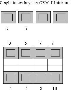
- 1. On the leftmost single-touch key below the CRM-III display, program the number for "Answer next in queue".
Dial 784 + 6891 + <press single-touch key>
- 2. On the second single-touch key to the left below the display, program the number for "Delete queue entry".
Dial 784 + 6892 + <press single-touch key>
Installation and Commissioning: AlphaCom
Hardware and Software Requirements
- AlphaCom exchange
- In order to have 4-line display information AMC-board version 02.10 or later is required (AMC SW 06.00 or later)
- Control Room Master III station (1000 700300/1000 700400)
- AlphaPro programming tool (1009291100 version 06.00 is needed to program all the features listed in this manual)
- Local +12V DC / 300 mA power supply for the station. (If ordering from Stentofon: EQPOW 20490 Mascot Power 6823/6-12)
- Station cable (Hirschmann plug: EPKAB98500; RJ45 modular jack: EPKAB98510).
Optional Extras
The voice message option for automatic acknowledgment to the call-in point requires an ASVP Board in the exchange.
Cabling
Connect the CRM-III station as shown in the figure on the right:
Audio
Connect the station cable to the station's abcd connector.
There are two alternative station cables:
- 3m cable with 6-pin Hirschmann plug.
- Connection:
- a - pin 1
- b - pin 2
- c - pin 4
- d - pin 6
- 3m cable with RJ45 modular jack.
- Connection:
- a - pin 3
- b - pin 6
- c - pin 7
- d - pin 8
Data
When the CRM-III is connected to the AlphaCom exchange, the station will receive the display data via the ab-wires - no additional data wires are required.
Power
Connect to the local power supply (12V DC).
Enable Data Communication with the station
Set the switches as described in section 4.4.
Programming the Exchange
To program the AlphaCom exchange, you must use the PC program AlphaPro. To have all the features mentioned in this manual you must have AMC software 06.00 or later in the exchange and AlphaPro program 06.00 for the programming.
Auto-load
- Four Call Request numbers are included in the default number series which is entered in the autoload:
| Dir.no. | Display Text | Priority |
| 622 | Alarm Request | 140 |
| 623 | Call Request | 100 |
| 624 | Alarm Request | 141 |
| 625 | Call Request | 101 |
- When you set station type = CRM-III, the Single-touch Keys on the CRM station are configured in the following way:
- 1. ANSW key - answers first call request in the queue.
- 2. NEXT key - steps to the next call request (scroll function).
- 9. Info key.
- 10. Subscriber Directory.
The other single-touch keys have no autoload programming.
Mandatory programming
- Go to Station programming
- Select wanted station (physical position where the CRM-III station is connected)
- Enter the wanted dir. no for the CRM-III station
- Enter wanted display text for the CRM-III station
- Set Station type = CRM-III
- Save
Optional programming
More Call Request numbers with different Priority levels
Priorities
There is the possibility for 256 priority levels for Call Requests and text messages.
On the CRM-III station the different priorities are announced in the following way (in addition to the position in the queue):
------------------------------------------------------------------------------------------
| Priority level | Notification at | Feature reminder:              |
|                | reception       |      (Tone)     | (Blinking light)   |
------------------------------------------------------------------------------------------
| 0 - 59         |   None          | Normal reminder |       Yes        |
-------------------------------------------------------------------------
| 60 - 119       |   Buzzer tone   | Normal reminder |       Yes        |
-------------------------------------------------------------------------
| 120 - 255      |   Buzzer tone   | Alarm reminder  |       Yes        |
-------------------------------------------------------------------------

