SIP2SIP Transcoding using Mediant 600
From Zenitel Wiki
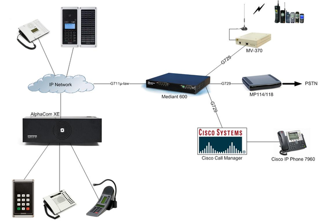
The Mediant 600 has the capability to transcode a SIP call from e.g. G711µ-law to G729. In this example the Mediant 600 is used to transcode G711µ-law to G729 between an AlphaCom XE 7 and an MP-114.
AlphaCom Configuration
AlphaWeb Configuration
Assign IP address to the AlphaCom XE Ethernet port(s)
Log on to AlphaWeb and enter a valid IP address on the Ethernet port. In the example below, Ethernet port 1 is used. Consult your network administrator to obtain the IP address.

Insert SIP Trunk licenses
The AlphaCom requires only 1 x SIP Trunk License for this configuration.
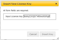
Log on to AlphaWeb and install the SIP Trunk license.
Firewall (filter) settings
Enable the SIP protocol on the desired Ethernet port (default enabled for Ethernet port1).

AlphaPro Configuration
Create a SIP Trunk Node
From the AlphaPro main menu, use the ‘+’ button next to the ‘Select Exchange’ dropdown list to create a new exchange. The exchange type must be set to ‘SIP Node’.
Set the parameters as shown in the image:

The SIP Trunk IP address must be identical to the IP address of the SIP
Gateway (i.e. Mediant 600).
Note: If the AlphaCom is configured with a SIP Registar node in addition to the
SIP Trunk node, the SIP Registar node must have a lower node number
than the SIP Trunk node.
Create AlphaCom/SIP Audio links
This paragraph is only relevant for AMC software 10.04 or earlier.
From AMC 10.05 the audio links are assigned dynamically whenever needed, and there is no need to specify the links in AlphaPro. Proceed Define the AlphaCom / SIP routing.
However, if you want to reserve VoIP channels for the SIP Gateway, you can do so by following the description below.
In Exchange & System > NetAudio use the Insert button to create one or several audio (VoIP) links between the AlphaCom and the SIP Gateway. The physical number specifies the VoIP channel and must be in the range 605 – 634 (start with 605). Normally the number of audio links will be equal to the number of phone lines connected to the SIP Gateway.

Define the AlphaCom / SIP routing
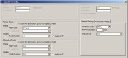
In Exchange & System > Net Routing use the Insert button to create a route between the AlphaCom and SIP Gateway. Set Preferred codec to G711u and RTP Packet Size to 20 ms.
Prefix and Global numbers
The telephone line can be accessed in different ways:
- Prefix number: Dial Prefix + Phone number. “Phone number” will be called
- Integrated Prefix number: Dial Prefix + Phone number. The prefix will be included as a part of the called telephone number.
- Global number: Dial the phone number without using prefix
Prefix number
The directory number must be programmed in the AlphaCom directory table with feature 81 and Node = SIP Trunk node number (100 in this example). In the “Parameter 2” field (“Collect N more digits (SIP)” in earlier AlphaPro versions) you must enter the maximum number of digits in a phone number.
When the prefix is dialed, the AlphaCom will wait for further digits. When the number of digits specified in the “Parameter 2” field (Collect N more digits (SIP in earlier versions of AlphaPro) are collected, a call setup message is sent to the SIP gateway. If fewer digits are entered, the AlphaCom will time out after 4 seconds, and the call setup message will be sent. You can also terminate the digit collection by pressing the M-key. The call setup message will then be sent immediately.
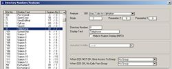
In the example to the right the directory number 0 is used as a prefix.
Dialing examples:
- 0 + 12345678: Telephone number 12345678 will be called
- 0 + 1234: After a 4 second timeout, telephone number 1234 will be called
- 0 + 1234 + M: Telephone number 1234 will be called
Integrated Prefix number
The directory number must be programmed in the AlphaCom directory table with feature 83 and Node = SIP Trunk node number (100 in this example). In the “Parameter 2” field (“Collect N more digits (SIP)” in earlier AlphaPro versions) you must enter the maximum number of digits in a phone number.
When the prefix is dialed, the AlphaCom will wait for further digits. When the number of digits specified in the “Parameter 2” field (“Collect N more digits (SIP)” in earlier AlphaPro versions) are collected, a call setup message is sent to the SIP gateway. If fewer digits are entered, the AlphaCom will time out after 4 seconds, and the call setup message will be sent. You can also terminate the digit collection by pressing the M-key. The call setup message will then be sent immediately.

In the example to the right the directory number 57 is used as a prefix.
Dialing examples:
- 57 + 12345678: Telephone number 5712345678 will be called
- 57 + 1234: After a 4 second timeout, telephone number 571234 will be called
- 57 + 1234 + M: Telephone number 571234 will be called
Global number

The directory number must be programmed in the AlphaCom directory table with feature 83 and Node = SIP Trunk node number (100 in this example). The “Parameter 2” field (in earlier AlphaPro version “Collect N more digits (SIP)”) must be left blank.
When the global number is dialed, the AlphaCom will immediately send a call setup message to the SIP gateway.
In the example to the right the directory number 12345678 is defined as a global number. When dialing this number a call setup message is sent to the SIP gateway, instructing it to call this phone number.
Update the exchange
Log on to the exchange and update the exchange by pressing the SendAll button.
Mediant 600 Configuration
A license SIP to SIP Mediation and Routing Application (SW/IP2IP/15) is required. With this license, the Mediant600 has 30 active Media Channels that can support 15 transcoding simultane sessions.
Restore to factory default settings

- With a paper clip, press and hold down the Reset button (located on the CPU Module) for at least 12 seconds (no more than 25 seconds)
- The device restores to factory default settings
- With a paper clip, press and hold down the Reset button (located on the CPU Module) for at least 12 seconds (no more than 25 seconds)
Access to the embedded web server
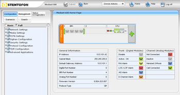
- The default Network parameter of the Mediant 600:
- IP Adress : 10.1.10.10
- Subnet Mask : 255.255.0.0
- Default Gateway : 0.0.0.0
- Connect your PC directly to the device, using an Ethernet Crossover cable
- Before the PC can access to the Mediant 600, the IP address of the PC must be changed to match the same subnet (e.g 10.1.10.11)
- To access the embedded web server, start your internet browser (e.g. Internet Explorer) and in the address field enter 10.1.10.10
- You will be prompted for a username and password (default):
- Username: Admin
- Password: Admin
- The Home Page page should now be displayed
Note: For the rest of configuration used the tree menu in Full mode
IP Configuration
RETURN TO THIS
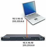

- In the "IP Settings" page (Configuration tab -> Network Settings menu -> IP Settings page) enter :
- IP Adress
- Subnet Mask
- Default Gateway
- Click "Submit" to apply the changes
- The IP address is immediately changed when pressing Submit, but it is not permanently stored
- Without resetting or powering off the device, you need to log on to the Gateway using its new IP address in order to Burn the new IP address to flash:
- Disconnect the PC from the Gateway
- Connect the Gateway and PC to the LAN. The PC and Gateway must be on the same sub-net
- Restore the PC’s IP address and subnet mask to what they originally were, and re-access the Gateway using the new assigned IP address
- Click "Burn" to permanently apply the changes
Add Software Upgrade Key
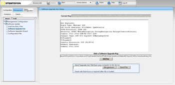
The license for SIP IP2IP must be uploaded as a Software Upgrade Key.
- In the "Software Upgrade Key Status" page (Management tab -> Software Update menu -> Software Upgrade Key page):
- Enter the license key in the "Add a Software Upgrade Key" field
- Click "Add Key"
- Burn
- Reset the device (Device Action -> Reset -> Reset)
Enable IP-to-IP Capabilities
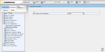
- In the "Applications Enabling" page (Configuration tab -> Protocol Configuration menu -> Applications Enabling page):
- From the "Enable IP2IP Application" drop-down list, select "Enable"
- Submit & Burn
- Wait the next step for Reset the device
Number of Media Channels
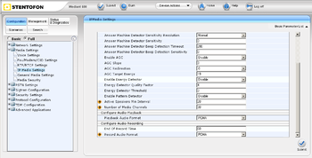
- In the "IP Media Settings" page (Configuration tab -> Media Settings menu -> IP Media Settings page):
- In the "Number of Media Channeles" field, enter the required number of media channels: 30 (maximum capacity of Mediant 600 is 60)
- Submit & Burn
- Reset the device (Device Action -> Reset -> Reset)
Proxy Sets Table
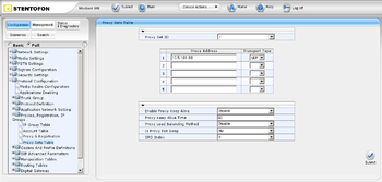
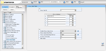
These "Proxy Sets" are later assigned to "IP Groups"
Note that the "Proxy Set" represents the actual destination to which the call is routed
- In the "Proxy Sets Table" page (Configuration tab -> Protocol Configuration menu -> Proxies,Registration,IP Groups submenu -> Proxy Sets Table page):
- Proxy Set ID#1 for AlpahCom XE7
- From the "Proxy Set ID" drop-down list, select "1"
- In the "Proxy Address" column, enter the IP address of the AlphaCom
- From the "Transport Type" drop-down list corresponding to the IP address entered above, select "UDP"
- Submit
- Proxy Set ID#2 for MP-114
- From the "Proxy Set ID" drop-down list, select "2"
- In the "Proxy Address" column, enter the IP address of the MP-114
- From the "Transport Type" drop-down list corresponding to the IP address entered above, select "UDP"
- Submit & Burn
IP Group Table
These "IP Groups" are later used by the device for routing calls
- In the "IP Group Table" page (Configuration tab -> Protocol Configuration menu -> Proxies,Registration,IP Groups submenu -> IP Group Table page):
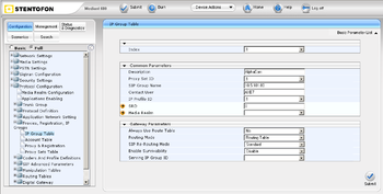
- IP Group #1 for AlpahCom XE7
- From the "Index" drop-down list, select "1"
- In the "Description" field, type an arbitrary name for the IP Group (e.g. AlphaCom)
- From the "Proxy Set ID" drop-down list, select "1" (For this "IP Group" communicate with the "Proxy Set" of the AlphaCom)
- In the "SIP Group Name" field, enter the IP Adress sent in the SIP Request From/To headers for this IP Group (AlphaCom's IP Adress)
- Contact User = name that is sent in the SIP Request contact header for this IP Group (e.g. AXE7)
- From the "IP Profile ID" drop-down list, select "1" (the IP Profile is configured later)
- Submit
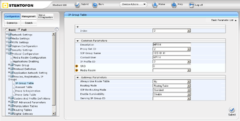
- IP Group #2 for MP-114
- From the "Index" drop-down list, select "2"
- In the "Description" field, type an arbitrary name for the IP Group (e.g. MP114)
- From the "Proxy Set ID" drop-down list, select "2" (For this "IP Group" communicate with the "Proxy Set" of the MP-114)
- In the "SIP Group Name" field, enter the IP Adress sent in the SIP Request From/To headers for this IP Group (MP-114's IP Adress)
- Contact User = name that is sent in the SIP Request contact header for this IP Group (e.g. MP114)
- From the "IP Profile ID" drop-down list, select "2" (the IP Profile is configured later)
- Submit & Burn
IP Profiles for Voice Coders
For use transcoding it's necessary create two IP Profiles for define two types of coders used.
These profiles are later used in the "Inbound IP Routing" and "Outbound IP Routing" tables.
- In the "Coder Group Settings" page (Configuration tab -> Protocol Configuration menu -> Coders And Profile Definitions submenu -> Coder Group Settings page):
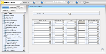
- Coder Group ID#1 for AlpahCom XE7
- From the "Coder Group ID" drop-down list, select "1"
- In the "Coder Name" drop-down list, select "G.711U-law" (Coder used by AlphaCom)
- Submit
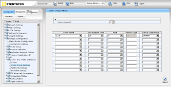
- Coder Group ID#2 for MP-114
- From the "Coder Group ID" drop-down list, select "2"
- In the "Coder Name" drop-down list, select "G.729" (Coder used by MP-114)
- Submit & Burn
- In the "IP Profile Settings" page (Configuration tab -> Protocol Configuration menu -> Coders And Profile Definitions submenu -> IP Profile Settings page):
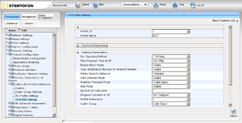
- Profile ID#1 for AlpahCom XE7
- From the "Profile ID" drop-down list, select "1"
- From the "Coder Group" drop-down list, select "Coder Group 1"
- Submit
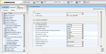
- Profile ID#2 for MP-114
- From the "Profile ID" drop-down list, select "2"
- In the "Coder Group" drop-down list, select "Coder Group 2"
- Submit & Burn
Inbound IP Routing
The "IP to Trunk Group Routing Table" it used for define the routing inbound IP-to-IP calls.
The table in which this is configured uses the IP Groups that you defined before.
- In the "IP to Trunk Group Routing Table" page (Configuration tab -> Protocol Configuration menu -> Routing Tables submenu -> IP to Trunk Group Routing page):
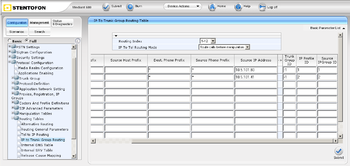
- Index#1 for AlpahCom XE7
- Dest Phone Prefix : enter the asterisk (*) symbol to indicate all destinations
- Source Phone Prefix : enter the asterisk (*) symbol to indicate all destinations
- Source IP Adress : enter the IP adress of the AlphaCom
- Trunk Group ID : enter "-1" to indicate that these calls are IP-to-IP calls
- IP Profile ID : enter "1" to assign these calls to "ProfileID#1" to use "G.711U-law"
- Source IP Groupe ID : enter "1" to assign these calls to the IP Group pertaining to the AlphaCom
- Index#2 for MP-114
- Dest Phone Prefix : enter the asterisk (*) symbol to indicate all destinations
- Source Phone Prefix : enter the asterisk (*) symbol to indicate all destinations
- Source IP Adress : enter the IP adress of the MP-114
- Trunk Group ID : enter "-1" to indicate that these calls are IP-to-IP calls
- IP Profile ID : enter "2" to assign these calls to "ProfileID#2" to use "G.729"
- Source IP Groupe ID : enter "2" to assign these calls to the IP Group pertaining to the MP-114
- Submit & Burn
Outbound IP Routing
The "Tel to IP Routing Table" it used for define the routing outbound IP-to-IP calls.
The table in which this is configured uses the IP Groups that you defined before.
- In the "Tel to IP Routing" page (Configuration tab -> Protocol Configuration menu -> Routing Tables submenu -> Tel to IP Routing page):
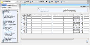
- Index#1 from AlpahCom XE7 to MP-114
- Src.IPGroupID : select "1" to indicate received (inbound) calls identified as belonging to the IP Group configured for AlphaCom
- Dest. Phone Prefix : enter the asterisk (*) symbol to indicate all destinations and callers respectively
- Dest.IPGroupID : select "2" to indicate the destination IP Group to where these calls are sent, to the MP-114.
- IP Profile ID : enter "2" to indicate the IP Profile configured for "G.729"
- Index#2 from MP-114 to AlphaCom XE7
- Src.IPGroupID : select "2" to indicate received (inbound) calls identified as belonging to the IP Group configured for MP-114
- Dest. Phone Prefix : enter the asterisk (*) symbol to indicate all destinations and callers respectively
- Dest.IPGroupID : select "1" to indicate the destination IP Group to where these calls are sent, to the AlphaCom.
- IP Profile ID : enter "1" to indicate the IP Profile configured for "G.711µ-law"
- Submit & Burn
AudioCodes MP-114 Configuration
Configure Network Parameters
Audiocodes MP-114/118 Configuration
Configure Network Parameters
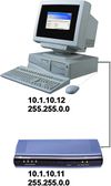

The AudioCodes MP-114/118 VoIP Gateway comes with default network parameters (factory default parameters).
Before you can set up the gateway in the network, you have to change the default IP address to a fixed IP address in your network environment. The unit is configured from a web browser, e.g. Internet Explorer or Navigator. Consult the network administrator to get the correct IP address.
Follow these steps:
- Load factory network parameters and reset the username and password to its default settings (username: Admin, password: Admin) by following these three steps:
1. Disconnect the Ethernet cable from the device.
2. With a paper clip or any other similar pointed object, press and hold down the Reset button (located on the rear panel) for about six seconds; the Fail LED turns red and the device restores to factory default settings.
3. When the Fail LED turns off, reconnect the Ethernet cable to the device.
- The VoIP Gateway will now get the IP address 10.1.10.11, subnet mask 255.255.0.0.
Change the IP address of your PC to 10.1.10.12, subnet mask 255.255.0.0.
Connect the LAN port of the PC to the Ethernet port of the Gateway. Use a crossed cable or connect the PC and the VoIP Gateway to a common switch using straight cables.
- Start your Web Browser and type 10.1.10.11 in the URL field.
- Type in user name Admin and password Admin. (Case-sensitive!)
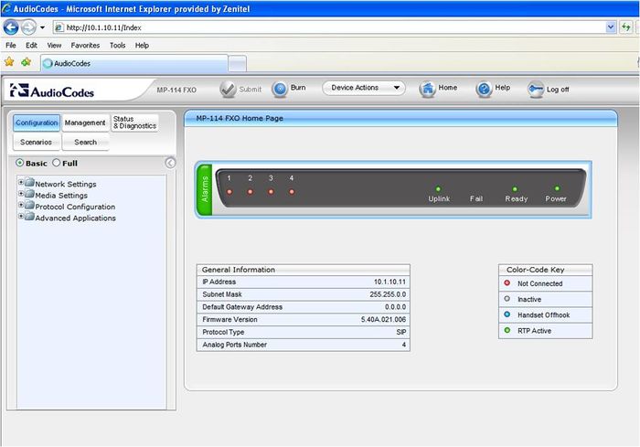
The Home page of the Web Interface:
IP Configuration
- In the 'IP Settings' page (Configuration tab > Network Settings menu > IP Settings page item) enter the IP Address, Subnet Mask and optionally the Default Gateway Address of the AudioCodes Gateway.
This IP address must be identical to the IP address of the SIP Trunk Node created in AlphaPro.
- Click Submit to apply the changes.
Note: The IP address is immediately changed when pressing Submit, but it is not permanently stored. Without resetting or powering off the device, you need to log on to the Gateway using its new IP address in order to Burn the new IP address to flash:
- Disconnect the PC from the Gateway.
- Reconnect the Gateway and PC to the LAN. The PC and Gateway must be on the same sub-net.
- Restore the PC’s IP address and subnet mask to what they originally were, and re-access the Gateway using the new assigned IP address.
- Click Burn to permanently apply the changes.
The AudioCodes MP-114 VoIP Gateway comes with default network parameters (factory default parameters).
Before you can set up the gateway in the network, you have to change the default IP address to a fixed IP address in your network environment. The unit is configured from a web browser, e.g. Internet Explorer or Navigator. Consult the network administrator to get the correct IP address.
Follow these steps:
- Load factory network parameters and reset the username and password to its default settings (username: Admin, password: Admin) by pressing the reset button located to the right of ethernet port II, and directly above the RS-232 port, labeled // for minimum 6 seconds.
- The VoIP Gateway will now get the IP address 10.1.10.10, submask 255.255.0.0.
- Change the IP address of your PC to 10.1.10.12, submask 255.255.0.0.
- Connect the LAN port of the PC to the Ethernet port I of the VoIP Gateway. Use a crossed cable or connect the PC and the VoIP Gateway to a common switch using straight cables.
- Start your Web Browser and type 'http://10.1.10.10' in the URL field. A log-in window appear, type in user name Admin and password Admin. (Case-sensitive!). Now the ‘Quick Setup’ screen opens.
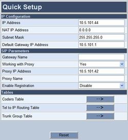
IP Configuration
Enter the IP Address and Subnet Mask of the AudioCodes Gateway.
This IP address must be identical to the IP address of the SIP Trunk
Node created in AlphaPro.
SIP Parameters
Set Working with Proxy to Yes.
Enter the IP address of the AlphaCom in the Proxy IP Address field.
Set Enable Registration to Disable.
Leave Gateway Name and Proxy Name blank.
- Click Reset button and OK button to apply the changes.
- Disconnect the PC from the Gateway.
- Reconnect the Ethernet port I of the VoIP Gateway to the LAN
- Reconnect the PC to the LAN.
- Restore the PC’s IP address and subnet mask to what they originally were, and re-access the Gateway using the new assigned IP address.
Audio Codec

In the Quick Setup screen, select Coders Table. Choose G.711U-law codec, 10 ms packet size and silence suppression Disabled.
- Press Submit to save changes.
About Saving Changes
The Submit button will save the data to the running volatile memory. The changes take effect on-the-fly. The changes will not survive hardware reset or power off.
To permanently save the configuration data you need to store the data to flash memory by selecting Maintenance from the main menu. Click the BURN button. A confirmation message appears when the save is completed successfully.
Note: Parameters proceeded by an exclamation mark (!) is not changeable on-the-fly and require that the device is reset.
Backup and Restore
The configuration of the AudioCodes Gateway can be stored to a file on your PC. Use the Configuration File menu to store or restore the configuration (Advanced Configuration > Configuration File).
AlphaCom to Telephone Network
Trunk Settings
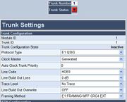
In Advanced Configuration > Trunk Settings you specify the properties of the trunk line. Select the protocol to be used for the trunk (Protocol Type), the trunk clock source (Clock Master), Line Code and physical framing to be used (Framing Method), and other relevant parameters.
Define a Trunk Group
In Protocol Management > Trunk Group you specify which channels to use on the E1 trunk, and assign the trunk to a Trunk Group ID and a Profile ID:

Trunk Group Settings
In Protocol Management > Trunk Group Settings you assign the rules for channel allocation:

IP to Trunk Group routing
In Protocol Management > Routing Tables > IP to Hunt Group Routing you specify the Trunk Group ID to use for call from IP (i.e. calls from AlphaCom E). In the example below all calls from AlphaCom are routed to Trunk Group 1.

Telephone Network to AlphaCom
Because the AlphaCom is defined as a Proxy Server in the SIP Gateway, you do not need to configure any Tel to IP Routing. The calling telephone number is automatically forwarded to the Proxy Server (i.e. the AlphaCom).
Miscellaneous Features
Incoming Calls in Private
Incoming calls from the telephone line can be forced to be in private ringing mode, independent of the private/open switch of the intercom station (available from AlphaPro/AMC 10.05).
- From AlphaPro 10.05: Check the flag Private Ringing from SIP in Exchange & System > System > Calls and Options.
- From AlphaPro 10.26: Check the flag Incoming calls from SIP in private ringing mode in Exchange & System > System > VoIP.
Door Opening Feature
During a conversation between a door station and a telephone, the telephone operator can activate the Door Opening feature in the AlphaCom by pressing digit 6.
SIP Gateway Feature
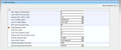
To enable digit actions from the telephone line during conversation, set 1st Tx DTMF Option to INFO(Cisco) in Protocol Management > Protocol Definition > DTMF & Dialing.
AlphaCom configuration
The Door Opening feature is programmed in the Event Handler. There are two separate events for the door opening feature, depending on who is the calling side:
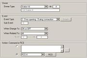
Calling from the telephone to the door
The Standard door opening event is used.
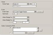
Calling from the door to the telephone
When the phone presses digit 6, the event type Event Trigger Feature
(15) is reported, with the digit 6 as sub event. The calling AlphaCom
station is Event Owner, and called SIP phone number and node number
is Related To. The RCO pulse time is specified as an additional
parameter in the RCO action string, i.e. RCO 3 ON 20 means pulse
RCO 3 for 2 seconds.
M-key Control from Telephone Network
The ‘*’ and ‘#’ buttons on the telephone can be used to control M-key function (simplex audio) ON or OFF:
- Press the ‘*’-key briefly and the M-key is turned ON
- Press the ‘#’-key briefly and the M-key is turned OFF
This can be useful for group call announcement from the telephone. The feature is enabled by setting 1st Tx DTMF Option to INFO(Cisco) in Protocol Management > Protocol Definition > DTMF & Dialing.
Transmit ‘*’ and ‘#’ from AlphaCom
The DTMF signals ‘*’ and ‘#’ will be transmitted to the line when DAK 0 (*) and DAK 1 (#) is pressed during a telephone conversation. (No programming is required).
Voice Switching in Noisy Environment
If the intercom station is located in a noisy environment, it might be difficult to switch the voice direction from the telephone towards the intercom station. However, there is a setting in the AlphaCom to overcome this problem.
In AlphaPro, go to Exchange & System > System > Voip. Set the flag Optimized voice duplex control when conversation with SIP trunk/stations. This flag is avaliable from AMC 10.05 and AlphaPro 10.26.
When the flag is set, the initial voice direction is forced to be from the intercom towards the telephone. When the phone operator starts to speak, the voice direction will switch towards the intercom station, regardless of the level of the audio signal from the intercom station. As soon as the phone operator stops speaking, the voice direction will switch back to the initial direction.
Make sure that the Echo Canceler is enabled in the SIP Gateway. (Protocol Management > Profile Definitions > Tel Profile Settings > Echo Canceler = Enable)
Feature Guide
- The telephone line is accessed either by dialing a:
- Prefix number: Dial Prefix + Phone number. Use M-key as a “Send” button, or wait for the number to be sent automatically.
- Global number: Dial the phone number without using prefix
- When pressing digits during connection, DTMF digits are sent (Call center etc.)
- The DTMF signals ‘*’ and ‘#’ will be transmitted when pressing DAK 0 (*) and DAK 1 (#)
- A complete phone number can be stored under a DAK key or a substation call button (From AMC 10.05)
- Program from station: 784 + <prefix> + <phone number> + M + DAK key. Example: 784 + 0 + 40002500 + M + DAK key
- Program from AlphaPro: I <prefix> P <phone number> M. Example: I 0 P 40002500 M
Call Transfer
- Incoming calls from the line can be transferred to another station
- From keypad: 2 + <intercom station> + 3
- From preprogrammed DAK: D 2 I 104 M M D 3
- Outgoing calls to the line can be transferred to another station
- From keypad: DAK8 + 2 + <intercom station> + 3
Call Forwarding
- An intercom call can be forwarded to a telephone
- From keypad: 71 + 0 + <phone number> + M
- From preprogrammed DAK: I 71 I 0 P 40002500
Search List
- A telephone number can be included in the Search List of a station.
- Format: I <prefix> P <phone number>. Example: I 0 P 40002500

