Configuration of the IP Vandal Resistant Substation TKIE
From Zenitel Wiki
The call button and station LED on the IP Vandal Resistant Substation TKIE must be configured.
ICX-AlphaCom Mode
Call Button
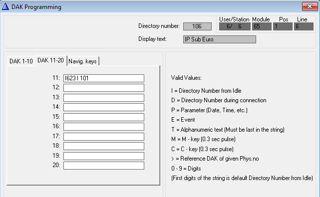
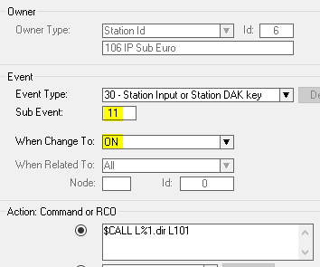
The call button is connected to input 1, and is by default set as input. Input 1 is programmed in AlphaPro as DAK 11 in DAK window, or as subtype 11 in event 30. Example shows DAK 11 doing Call Request to station 101:
Example shows input 1 calling station 101 using event 30:
LED Settings
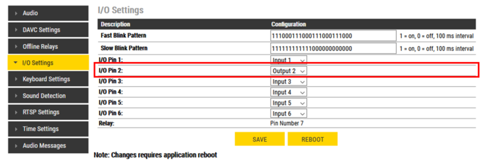
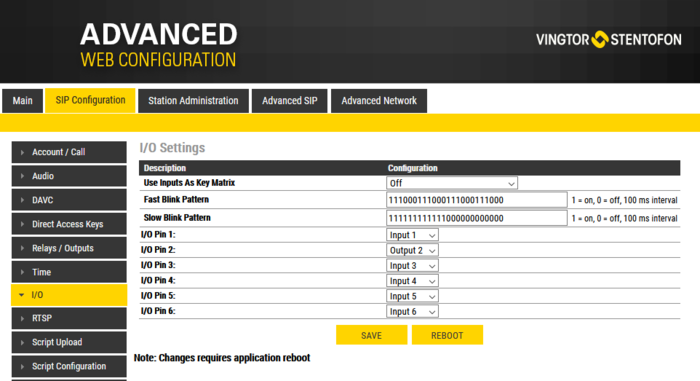
Log into the station webserver and navigate to the I/O settings. The station LED is from factory wired to output 2.
Choose I/O and set it as Output.
Control the LED
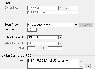
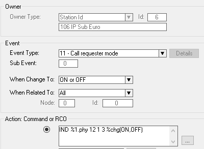
Use the event handler and define situations where the station LED shall be lit:
- Microphone active:
- Call Request and Ringing Group call with blinking LED:
IC-Edge Mode
Call button
The call button is connected to input 1, and is by default set as input. The input is programmed in Edge Controller -> System Configuration -> Direct Access Key (DAK) and Buttons and Inputs. The example below shows how to set up a call to directory number 101. The conversation will be ended if input or call button is pressed during conversation.
LED Settings
Advanced configuration mode must be enabled to make the following changes.
Log into the station webserver and navigate to the I/O settings. The station LED is from factory wired to output 2.
Choose I/O and set it as Output.
Control the LED
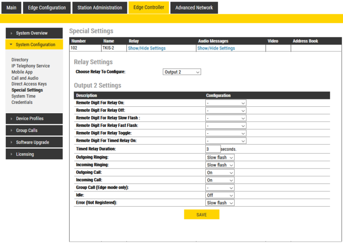
In Edge controller, go into System Configuration -> Special Setting and select Relay setting.
Choose to configure output 2 in the listbox. The recommended settings are shown below:
SIP Mode
Call Button
The call button is connected to input 1, and is by default set as input. The input is programmed in SIP Configuration -> Direct Access Key (DAK). The example below shows how to set up a call to directory number 101. The conversation will be ended if input or call button is pressed during conversation.
LED Settings
Advanced configuration mode must be enabled to make the following changes.
Log into the station webserver and navigate to the I/O settings. The station LED is from factory wired to output 2.
Choose I/O and set it as Output.
Control the LED
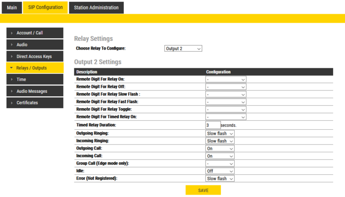
In the station web server, go into SIP Configuration -> Relays/Outputs.
Choose to configure output 2 in the listbox. The recommended settings are shown below:


