IP Flush Master -V2 Board Connectors
From Zenitel Wiki
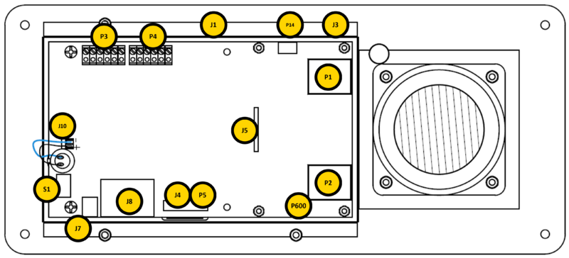
This chapter gives details about connections and indications for:
| Item | Description | Comment |
| P3 | Pluggable screw connector | * 1/2 = Connection to internal loudspeaker (8ohm) * 3/4 = Relay * 5/6 = Not in use |
| P4 | Pluggable screw connector | * 1/2/ = Input 1-3 * 4 = Common * 5/6 = Station LED (5=A, 6=C) |
| J1 | D48 Expansion Module | RJ45 Connector to connect D48 modules, via I2C bus. |
| P14 | External loudspeaker | 3-pin screw connector for 8 ohm loudspeaker (max 5W). Operates in parallel with internal speaker. |
| J3 | 5VDC | 5 volt DC output |
| P1 | LAN Port | 10/100Mbps RJ-45 port for connection to the network. Supports PoE (802.3af). Draws power from either spare line or signal line. |
| P2 | AUX Port | 10/100Mbps RJ-45 port for for auxiliary equipment such as PC and IP camera. PoE is not forwarded to this port. |
| P600 | External Power Supply | 2-pin screw connector for connecting external 24-48VDC power supply. Max 300mA. |
| J5 | Display | 20-pin ZIF connector for LCD display. Separate display panels are available as a kit of 5 units (order no. 1008099000). |
| P5 | Keyboard | Solderpoints See details further down. |
| J4 | Keyboard | 18 pin ZIF connector. See details further down. |
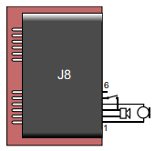
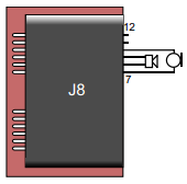
| J8 | Handset/Headset | Dual RJ11 for Handset and Headset. See details further down. |
| J7 | Gooseneck | 3-pin header for connecting gooseneck microphone. 1 is +, 2 is - and 3 is GND. |
| S1 | Microphone selector | Slide switch to select internal microphone (int) or gooseneck microphone (ext) |
| J10 | Microphone | Internal microphone. Pin 1 is + and 2 is -. |
Inputs

|
|
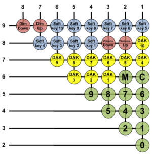
Keyboard matrix
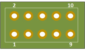
P5 pinnings:
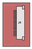
J4 connector In software you can choose between four different matrix types, see Keyboard Settings.
18-pin ZIF-connector for keyboard. The keyboard may have up to 10 dialling keys, M and C keys, 10 DAK keys, 10 soft keys, volume up/down and light dim up/down keys connected in a matrix according to the drawing.
- J4/10 DAK1 Green LED
- J4/11 DAK1 Red LED
- J4/12 DAK2 Green LED
- J4/13 DAK2 Red LED
- J4/14 DAK3 Green LED
- J4/15 DAK3 Red LED
- J4/16 DAK4 Green LED
- J4/17 DAK4 Red LED
- J4/18 Common +3.3 V
Handset and Headset
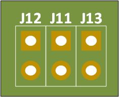
Handset can optionally be connected via J11, J12 and J13.
J11, J12 & J13 - Handset
Pin header for handset connection. Same as J8 pin 1 - 6.
- J11 Pin 1 Spk+
- J11 Pin 2 Spk-
- J12 Pin 1 Mic+
- J12 Pin 2 Mic-
- J13 Pin 1 OFFHOOK
- J13 Pin 2 GND
Handset:
- Pin 1 Mic+
- Pin 2 Spk+
- Pin 3 Spk- (0 V)
- Pin 4 Mic-
- Pin 5 Hook-switch (must be connected to pin 6 via a switch)
- Pin 6 Hook-switch Ground
Headset:
- Pin 7 Mic+
- Pin 8 Spk+
- Pin 9 Spk-
- Pin 10 Mic-
- Pin 11 PTT Ground
- Pin 12 PTT (Not currently supported by SW)


