Audio Configuration (Zenitel Connect Pro)
From Zenitel Wiki
Contents
Introduction
Audio settings for a device are done from the Zenitel Connect Pro web interface. From the Devices and Connections section, select Configuration. Select one or several devices to configure, the click the Audio icon.
 |
| Audio Settings for device |
There are separate sections for:
- Audio outputs
- Audio inputs
- Audio Lines (=audio processing)
- AVC (Automatic Volume Control)
It is possible to multi-select devices for audio configuration; only those parameters which are common to all selected devices will be available for inspection and editing. Parameters which are not configured the same are indicated by . Parameters which are common, but have a different range will only allow a setting in the common part of that range when multiple devices have been selected.
Accessory
For intercom devices that support accessories, one can choose what type of accessory is connected to the device from a drop-down menu. Available options depends on device type:
- No accessory
- Handset
- Handset w/Off-hook
- Handset w/Off-hook (Normally Closed)
- Handheld microphone
- Headset
- Headset w/Autodetect
Audio Outputs
In the Audio Outputs section it is possible to set the output gain for the different loudspeaker and line types which the device supports.
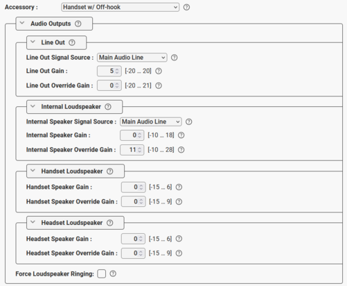 |
| Audio Outputs settings available for an industrial TFIE station |
Internal Loudspeaker: The built-in speaker in intercom stations
- Internal Speaker Signal Source: Select the "audio source" for playing in the speaker:
- Main Audio Line: Play audio from VoIP signal (default)
- Pure Line In Signal: When the device is in idle, play audio from the Line In input. When the device is in a call, play audio from the VoIP signal
- Pure Line In+GPIO: When the device is in idle, play audio from the Line In input if Input 6 is active. When the device is in a call, play audio from the VoIP signal
- Internal Speaker Gain: Sets the regular gain/volume on the internal speaker.
- Internal Speaker Override Gain: Sets the volume when the Volume Override feature is active.
Line Out: The Line Out is a 0dBm analog line out for connection of hearing loop amplifier, PA amplifier, recorder etc.
- Line Out Signal Source: Additional options available when "No Accessory" is selected:
- Main Audio Line: Play audio from the VoIP signal (default)
- Pure Mic Signal: Play audio from the microphone without any signal processing
- Processed Mic Signal: Play audio from the microphone with signal processing
- Line Out Gain: Sets the regular gain/volume on the Line Out signal.
- Line Out Override Gain: Sets the volume when the Volume Override feature is active.
Handset Loudspeaker: Applicable if a handset is connected to the device
- Handset Speaker Gain: Sets the regular gain/volume on the handset speaker.
- Handset Speaker Override Gain: Sets the volume when the Volume Override feature is active.
Headset Loudspeaker: Applicable if a headset is connected to the device
- Headset Speaker Gain: Sets the regular gain/volume on the headset speaker.
- Headset Speaker Override Gain: Sets the volume when the Volume Override feature is active.
External Loudspeaker: The IP Flush Master, IP-CROR and the TFIX-V2 series of stations have an additional output for external loudspeaker. This loudspeaker output needs to be enabled. Volume can then be configured separately from the internal speaker:
- External Speaker Output Type:
- Not connected: Disable loudspeaker output (default)
- Standard Loudspeaker: Enable loudspeaker output
- External Speaker Gain: Sets the regular gain/volume on the external speaker.
- External Speaker Override Gain: Sets the volume when the Volume Override feature is active.
Mute Speaker While Analog Mic is Active: On so devices there is an option to switch between the internal digital mic and an external microphone by activating an input. This makes it possible to connect a handset or headset to TCIS/TCIV+, and connect the hook-switch of the handset to the input. When this flag is enabled, the loudspeaker will be muted when the analog microphone (e.g. the handset) is active.
Force Loudspeaker Ringing: Enable the ringing signal in the Internal Loudspeaker when receiving an incoming call and a headset, handset or external loudspeaker is being used.
Audio Inputs
In the Audio Inputs section you can select the input gain for the internal microphone, and other input sources that might be connected to the device.
- If the device has headset or handset connected, the gain from this microphone can be adjusted separately.
- Headset Microphone: One can select between Electret Mic or Dynamic Mic.
- Line In: On devices with analog Line In (e.g. TKIE kit), you can choose to use the Line In as input source (only when "No Accessory" is selected) instead of the Internal Microphone by setting Line In Input Type = Line In 1 vrms.
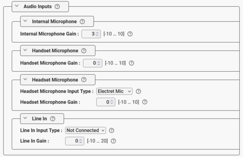 |
| Audio Inputs configuration |
- On devices with a digital MEMS microphone (e.g. TCIS and TCIV+ stations), one can choose to use an external electret mic instead of the built-in MEMS microphone:
 |
| Choose what type of microphone to use |
- Digital Mic (default): Use the built-in MEMS microphone
- Electret Mic: Use an electret microphone connected to the the analog mic input instead of the digital microphone.
There is also an option to switch between the internal digital mic and an external microphone by activating an input. This makes it possible to connect a handset or headset to TCIS/TCIV+, and connect the hook-switch of the handset to the input. One can choose which input to use for the hook-switch.
- I/O Pin A>D Switch: When the input is active the analog mic input is enabled. When the input is deactivated, the digital mic is enabled. The input must be configured as "Input" in the IO Settings page. Use case is connection of a handset, where the hook-switch is connected to the input.
- I/O Pin A>D Switch (until call-end): When the input is triggered e.g. by a push button, the analog mic input is enabled. The analog mic input will remain active until the call is ended, then the digital mic is enabled. Use case is connection of a headset, where a push-button connected to the input switches the audio to the headset during the call.
Audio Lines (Digital Signal Processing Configuration)
Various Digital Signal Processing algorithms are available under Audio Lines > Main Line > Digital Signal Processing Configuration.
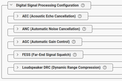 |
| Digital Signal Processing options |
Digital signal processing is used to enhance the audio experience, especially when an intercom is located in an acoustically challenging environment, for instance a noisy location or somewhere where there is a lot of echo. Digital signal processing alters the contents of the audio signal and may by doing so introduce unwanted artifacts, especially when high levels of processing are required. In these cases, the experienced audio quality might become sub-optimal.
AEC (Acoustic Echo Cancellation)
Acoustic Echo is when you during a call can hear your own voice in return, with more or less volume, and more or less delay. The echo can range from simply annoying to absolutely unbearable, and may result in callers not understanding each other and important information being missed.
The purpose of the AEC feature is to remove this echo. AEC is supported by all Zenitel IP devices, and is by default active. Zenitel IP intercoms have been calibrated from factory, and the AEC level is by default set to the most suitable value. Hence there is normally no need to alter the default settings.
AEC is by default enabled, but can be disabled. There are 5 possible levels:
- Low
- Moderate - the default value when AEC is enabled
- High
- Half Duplex - The connection provides a voice switched experience, as the loudspeaker will be muted when speaking into the microphone.
- WebRTC AEC3 (available in some models) - a different algorithm which may provide good results on some occasions
High or Half Duplex can be used in noisy or acoustic challenging environments, or in customized stations without optimal acoustic design, where one is experiencing issues with echo, chopping audio or one-way audio.
Some parameters effecting the acoustic echo cancellation:
- Loudspeaker volume
- Microphone sensitivity
- Distance between speaker and microphone
- Mechanical design (e.g. vibrations, speaker and mic mounting)
- Environment (e.g. reflecting surfaces)
ANC (Active Noise Cancellation)
Some devices may be installed in a noisy environment, with noise from e.g. an air conditioner, a factory floor or a truck engine. The purpose of the Active Noise Cancellation is to cancel out the surrounding background noise and at the same time keep the voice signal intact. The Active Noise Cancellation feature is by default enabled, hence there is normally no need to do any configuration.
ANC is by default enabled, but can be disabled. When enabled, there are 4 levels to select from:
- Low
- Moderate - the default value when ANC is enabled
- High
- Very High
AGC (Automatic Gain Control)
The purpose of the Automatic Gain Control (AGC) feature is to try to maintain a constant microphone signal level, despite variations in the speech level because the talker is at a distance from the intercom station, or talking with a low voice. The AGC feature is providing more amplification to weak signals and less amplification to strong signals thus maintaining a constant signal amplitude level at the output.
- Enable AGC: Enable/disable the AGC component which brings the microphone signal to an appropriate range
- AGC mode: Algorithm type.
- Digital SW AGC - Used for the majority of use cases.
- Analouge HW AGC (noisy profile) - is available only on Turbine devices using analogue microphone. Should basically be used for "Push to Talk"/"Talk back" applications and not in Open Duplex modes
- Analouge HW AGC (quiet profile) - is available only on Turbine devices using analogue microphone. Should basically be used for "Push to Talk"/"Talk back" applications and not in Open Duplex modes
- AGC gain profile: The target signal gain level. "Standard" shall aim to keep a "nominal voice signal level" at approx -23 dBFS. The other options will target increasingly higher signal levels. Use with caution.
- Standard
- Moderate
- High
- Very high
- AGC speed: Attack and decay rates of the algorithm.
- Slow
- Fast
FESS (Far-End Signal Squelch)
The purpose of the Far End Signal Squelch (FESS) feature is to mute the speaker of the device when the incoming audio signal is very low.
This feature is typically used when a device is constantly playing an audio stream, and there is not always voice/audio present. In silent periods a low noise might be heard from the speaker. This is normally not noticeable, but if the user is using a headset, or the device is an overhead speaker playing the audio, this can be noticeable and a bit annoying. In such cases the FESS feature can be used to completely mute the speaker when the audio signal is below a set threshold.
The FESS feature is by default disabled. When enabled, these are the configuration options:
- FESS Threshold: Signals below the set level are suppressed. Range: -92 to 0 dBFS (Decibel of Full Scale)
- FESS Activation Delay: Time (in milliseconds) before the squelch is activated. Range: 0 to 10000 ms
Loudspeaker DRC (Dynamic Range Compression)
The Dynamic Range Compression (DRC) is an audio signal processing function that helps even out the loud and quiet parts. Lower signals will get gain applied, but not more than there is headroom for up to digital full scale.
For intercom devices and IP Speakers the DRC will normally have a good effect on regular speech signals, and will often increase the loudspeaker output noticeably. For already maximized signals, such as prerecorded alarm tones, DRC will have little or no effect.
Enabling DRC may also have a positive effect on the Acoustic Echo Cancellation (AEC) performance of the device as it might not be necessary to increase the overall volume, which would cause a stronger echo.

|
|
The DRC feature is by default disabled. When enabled, one can set the DRC gain (0 - 20 dBA). The gain specifies the maximum gain which can be added to the signal. Note that some signal clipping may occur if the DRC is configured to use high gain.
AVC (Automatic Volume Control)
When the Automatic Volume Control (AVC) feature is active, the microphone of the device is constantly measuring the ambient noise. The AVC feature automatically adjusts the volume of the loudspeaker to compensate for the ambient noise in an effort to make the audio signal better heard and understood above the noise. The AVC will perform better if the "Internal Speaker Volume" is set to a fairly low level, as this will give the AVC more headroom for adjustments. The AVC feature works very well in combination with the Dynamic Range Compression (DRC) feature.
Note that the volume is not adjusted while the speaker is playing audio. Adjustments are made in silent periods (min. 100 ms silence required).
AVC is disabled by default. When enabled, the default parameters might be adjusted if required:
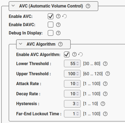 |
| AVC configuration - Default parameters |
- Enable AVC: Check the box to enable Automatic Volume Control.
- Debug in Display: When enabled the station shows current volume level in the OLED display (applicable to TCIS-4, TCIx-5 and TCIx-6 stations). Very useful during testing or demo of the AVC feature.
- Enable AVC Algorithm: Check this box
- Lower Threshold: Threshold level for the AVC to start working. Valid range: 30-80 dBA. Default is 55 dBA.
- Upper Threshold: Threshold level for the AVC to stop working. Valid range: 60-120 dBA. Default is 100 dBA.
- Attack Rate: How quickly the AVC adjusts gain on raising ambient audio level. Range: 1..100 dBA/sec. Default is 10 dBA/sec.
- Decay Rate: How quickly the AVC adjusts gain on falling ambient audio level. Range: 1..100 dBA/sec. Default is 10 dBA/sec.
- Hysteresis: Hysteresis around previous set ambient audio level before doing adjustments. Range: 1..10 dBA/sec. Default is 3 dBA.
- Far-End Lockout Time: The AVC adjustments are locked while the device is playing audio. When there is a pause in the audio (silence), adjustment commences after this lockout-time. Range: 1..100. Resolution is 100 ms. Default is "1" (= 100 ms).
Distributed Automatic Volume Control (DAVC):
The Distributed Automatic Volume Control (DAVC) is an algorithm which is using one or more microphones ("AVC Source") to measure the ambient audio/noise level, and adjusts the loudspeaker output level of the PA amplifier ("AVC Receiver") according to the ambient audio level.
- The AVC Source is the input device with the listening microphone used for measuring the ambient noise level. This is typically an EINS-1 microphone unit, but any Turbine Device with microphone can be used. The AVC Source sends its microphone measurements to the AVC Receiver.
- The AVC Receiver is the output device that is used for playing audio, typically an ENA amplifier, or a PA Interface such as a TKIS-kit or TKIE-kit.
DAVC is not operating while audio is actively playing at the AVC Receiver. With the default configuration, it needs minimum 100ms of silence to be able to adjust the gain by 1dB. This should work just fine with normal speech, but AVC will not adjust while playing constant music.
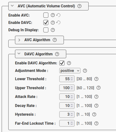
DAVC is disabled by default. When enabled, these settings are available:
 |
| DAVC configuration - Default parameters |
- Adjustment Mode:
- Positive Mode: Gain adjustment is from zero at AVC threshold level and adjusted positive. AVC Receiver should have a low base gain.
- Negative Mode: Gain adjustment is from zero at AVC max level and adjusted with negative gain downwards. AVC Receiver should have a high base gain.
- Lower Threshold: Threshold level for the AVC to start working. Valid range: 30-80 dBA. Default is 55 dBA.
- Upper Threshold: Threshold level for the AVC to stop working. Valid range: 60-120 dBA. Default is 100 dBA.
- Attack Rate: How quickly the AVC adjusts gain on raising ambient audio level. Range: 1..100 dBA/sec. Default is 10 dBA/sec.
- Decay Rate: How quickly the AVC adjusts gain on falling ambient audio level. Range: 1..100 dBA/sec. Default is 10 dBA/sec.
- Hysteresis: Hysteresis around previous set ambient audio level before doing adjustments. Range: 1..10 dBA/sec. Default is 3 dBA.
- Far-End Lockout Time: When playing audio in AVC zone (far-end-signal) AVC adjustments are locked. When there is a pause in the far-end-signal, adjustment commences after this lockout-time. Range: 1..100. Resolution is 100 ms. Default is "1" (= 100 ms).

