Integration with ASL PAVA using the IP-LCM unit
From Zenitel Wiki
To have multiple zone selection and only audio line from ICX-system to the Vipedia system an IP-LCM is used. This article will describe three use cases with their needed wiring and event configuration.
Contents
Static zone selection
The audio line output of the IP-LCM is directly connected to an audio input on the Vipedia. When you call a group call number in the ICX-AlphaCom a relay on the IP-LCM is activated. This in turn will set up a fixed route in the Vipedia. Calling a different group call number will trigger a different relay, setting up a different route.
In this way you can select different zones in the Vipedia system by calling different group calls. The IP-LCM must be a member of all group calls used.
Wiring the hardware
To use the IP-LCM with the Vipedia it is recommended that you use the BMB01. Using the BMB01 will save the GPIO on the Vipedia. One BMB01 and one IP-LCM can be mounted next to each other on a DIN-rail and fits within 19 inch. The audio line output of the IP-LCM is directly connected to an audio input on the Vipedia.
Wiring the BMB01 inputs to the relays of the IP-LCM
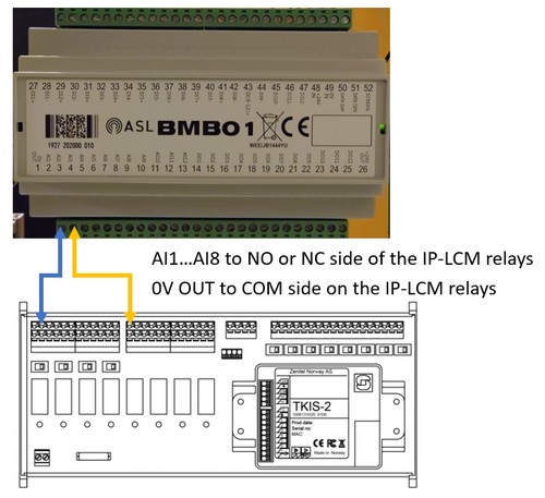
To wire the relay contacts of the IP-LCM to the BMB01 you need to take the 0V OUT terminal (#1) of the BMB01 and connect it to all the COM connections of the relays you want to use. Then depending on whether you want Active High or Active Low take either the NC of NO side of the relay contact and wire it to the input terminals AI1 to AI8 (#2 to #9). If you need to use relays 5 to 8 of the IP-LCM you need to set the switches of those relays to "dry contact", which is to the near edge of the board. If you need to monitor the connection we refer to the BMB documentation.
Wiring the audio output of the IP-LCM to the Vipedia audio input
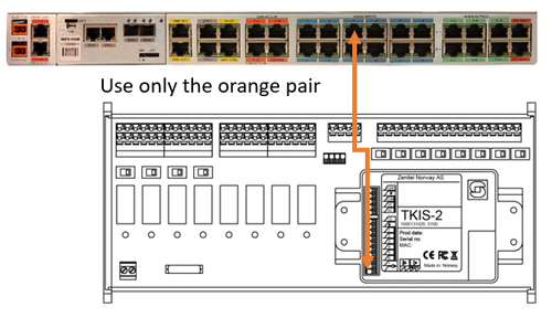
Take a shielded CAT5 patch cable and strip the end. You can remove all pairs except the orange pair. The white/orange wire connects to the (+) side of the audio output on the IP-LCM and the orange wire to the (-) side. The RJ45 connector on the other side of the CAT5 patch cable can be directly inserted into the correct audio input on the Vipedia.
Event configuration in ICX
In the ICX-AlphaCom we need to configure one relay of the IP-LCM to operate when one group call is made, and another relay to operate when a different group call is made. This is done in the Event Handler.
In the example below the:
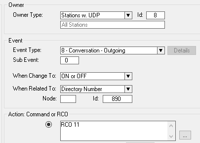
- Remote Control Output RCO 11 will be triggered when any station (= UDP 8) is calling group call 890.
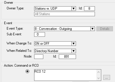
- Remote Control Output RCO 12 will be triggered when any station (= UDP 8) is calling group call 891.
- The IP-LCM must be a member of both group call 890 and 891.
The logical RCOs 11 and 12 must be mapped to the physical relays of the IP-LCM. This is done in Exchange & System > RCO table.
Configuration in Vipedia
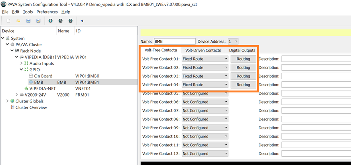
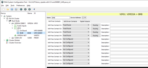
In the SCT (System Config Tool) the BMB01 inputs will be setup with fixed routes on the Volt-Free Contacts. The RCO that is triggered on the IP-LCM is connected to an input of the BMB01. By using a Fixed Route the Vipedia will then set up a correct route to the outputs and zones.
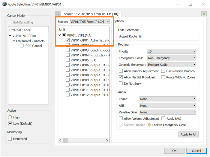
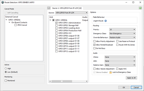
The Route will be configured from the audio input that the IP-LCM is connected to to one or more audio outputs.
Dynamic zone selection
With dynamic zone selection you each button on a ECPIR or DAK panel toggles a relay on the IP-LCM. these select routes in the Vipedia. The PTT button then sends the audio to the selected routes.
Wiring the hardware
The wiring for dynamic zone selection is the same as with static zone selection.
Linking ECPIR panel to IP-LCM
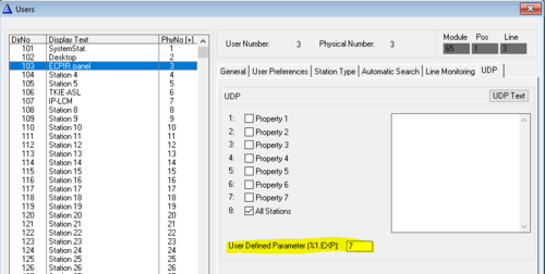
In Users & Stations, select the ECPIR panel from the listbox. Under the UDP tab, enter the physical number of the IP-LCM module to be controlled by this ECPIR panel.
Event configuration in ICX
For the dynamic zone selection to work you need three events to be programmed.
Zone selection from ECPIR panel
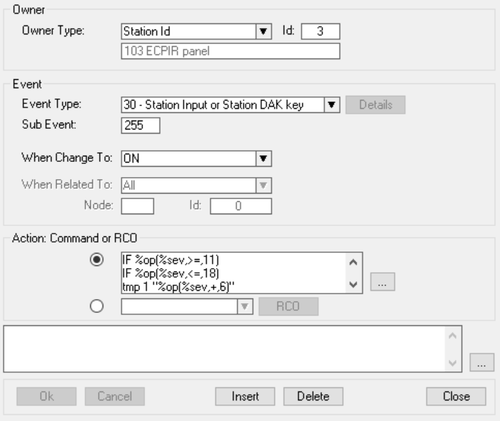
The first event is triggered by pressing one of the DAK keys on the ECPIR or DAK panel. The event will then check status of the corresponding on the IP-LCM and toggle its state. In the same event the indicating LED on the ECPIR or DAK panel will be toggled to blinking or off accordingly.
Action commands:
IF %op(%sev,>=,11)
IF %op(%sev,<=,18)
tmp 1 "%op(%sev,+,6)"
IF %prco(%1.exp,%tmp(1))
IND %1.phy %sev 2 3 OFF
$SET_IPRCO N%1.exp U%tmp(1) U0
STOP
ENDIF
IND %1.phy %sev 2 3 ON
$SET_IPRCO N%1.exp U%tmp(1) U1
ENDIF
ENDIF
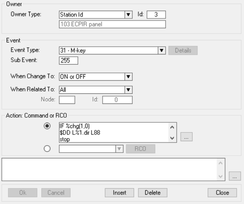
PTT button on ECPIR panel
When the PTT button is pressed, this event will dial a group call. The IP-LCM must be a member of this group. When the button is released the call will be cancelled.
Action commands:
IF %chg(1,0)
$DD L%1.dir L88
STOP
ENDIF
$DISCON_ST L%1.dir U0
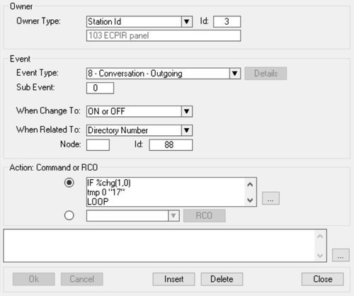
LED status on ECPIR panel
The third event checks the status of the IP-LCM relays when the groupcall starts. The corresponding LED's on the ECPIR panel will go from blinking to steady lit. When the groupcall ends all relays and LEDs will be turned off.
Action commands:
IF %chg(1,0)
tmp 0 "17"
LOOP
IF %prco(%1.exp,%tmp(0))
IND %1.phy %op(%tmp(0),-,6) 2 3 OFF
IND %1.phy %op(%tmp(0),-,6) 2 1 ON
ENDIF
tmp 0 "%op(%tmp(0),+,1)"
IF %op(%tmp(0),=,25)
BREAK
ENDIF
ENDLOOP
STOP
ENDIF
IND %1.phy 0 0 0
tmp 0 "17"
LOOP
$SET_IPRCO N%1.exp U%tmp(0) U0
tmp 0 "%op(%tmp(0),+,1)"
IF %op(%tmp(0),=,25)
BREAK
ENDIF
ENDLOOP
Configuration in Vipedia
The input of the BMB01 have to be configured to select the appropriate routes. In the tab Volt-free contacts you choose for every input you use "fixed route".
And under the button Routing you set up the route configuration.
Feedback to ICX-AlphaCom on selected zones in Vipedia
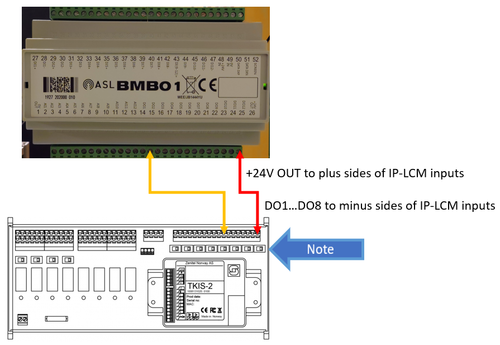
To get feedback into the ICX-AlphaCom what routes are selected in the Vipedia you need additional wiring from the outputs of the BMB01 to the IP-LCM inputs.
Wiring the BMB01 outputs to the IP-LCM inputs
Take the 24V OUT terminal (#26) and wire it to al the (+) sides of all the inputs on the IP-LCM you want to use. The (-) sides of all the inputs should be wired to the output terminals DO1 to DO8 (#14 to #21). The switches of the used inputs on the IP-LCM should all be set to "Active signal" (switch set to the relay side of the board).
Event configuration in ICX-AlphaCom
On ECPIR panel
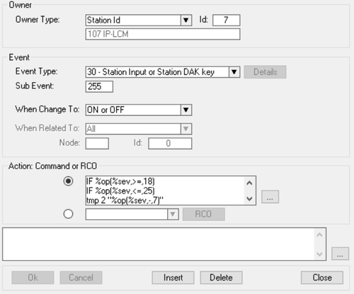
There is only one event to be configured in ICX-AlphaCom that is triggered by the inputs of the IP-LCM.
Action commands:
IF %op(%sev,>=,18)
IF %op(%sev,<=,25)
tmp 2 "%op(%sev,-,7)"
IND 3 %tmp(2) 1 1
ENDIF
ENDIF

|
In the code IND 3 %tmp(2) 1 1 above the digit "3" is the physical number of the ECPIR panel. As this is hardcoded, you need to change this number according to the physical number of the ECPIR panel. |
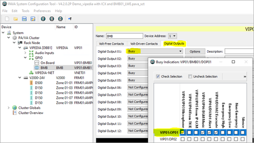
Configuration in Vipedia
In the Vipedia the outputs of the BMB must be configured to be active when a zone is busy.

