Difference between revisions of "APWR Power supply"
From Zenitel Wiki
| Line 47: | Line 47: | ||
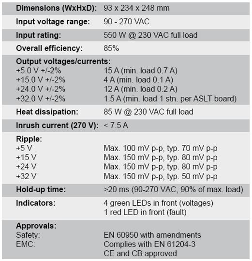
== Specifications == | == Specifications == | ||
[[Image:APWR Specification.jpg]] | [[Image:APWR Specification.jpg]] | ||
| + | |||
| + | [[Category:AlphaCom E System]] | ||
Revision as of 23:45, 26 November 2007
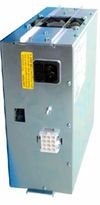
The APWR power supply has four DC outputs delivering the desired voltages for AlphaCom and AlphaCom E exchanges. The power supply is able to supply a STENTOFON AlphaCom exchange equipped with maximum 17 ASLT subscriber cards, which is a fully equipped AlphaCom E20 module. In an AlphaCom E26 exchange, two power supplies are required to supply the complete module; a third can be installed for redundancy.
The power supply is easy to install and connect due to the use of Universal AMP Mate’nLock type output connectors.
WARNING: This 100 9703 000 power supply is incompatible with the older 100 9701 000 supply. Do not put power supplies of different types into the same exchange module.
Features
- Made for AlphaCom 80+, AlphaCom 138, AlphaCom E20 and AlphaCom E26
- Provides +5 V, +15 V, +24 V, and +32 V
- Universal voltage input range from 90 to 270 VAC
- Each power supply serves 102 standard stations
- Can be connected in parallel for load sharing and redundancy
- Potential-free alarm output to warn of power failure
- The power supply shuts down if one voltage fails for protection against overheating
- Power factor correction for efficient energy use
- Over voltage and short circuit protected
- Plug connector for DC outputs - no screws
- International safety approvals
- LED indicator per output voltage and fault
- Built-in cooling fan
Mounting
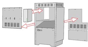
- Remove the upper front cover
- Remove the back covers
- Slide the power supply into the rails in the upper compartment from the front side
- Leave the power unit front flush with the exchange cabinet front
Connection
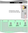
- Plug the internal power cable to the power supply
- Route the cable through the holes in the main frame
- Connect the cable to a free power connector on the back plane
- Plug the female end of the mains cable into the power supply and the other to the mains outlet in the cabinet’s upper compartment
Indicators
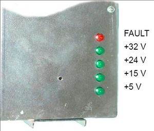
- The green indicators are lit when the voltages are correct.
- The red indicator is lit only if there is a fault in the power.
- This indicator is not visible when the front cover is mounted.

