CRM V - Control Room Master
From Zenitel Wiki

The CRM-V Station is designed for control room applications. The station consists of a main module (IP Flush Master), which can be extended with up to two IP DAK-48 Units and a handset module.
This article describes how to install and configure the CRM-V station.
Contents
Available items
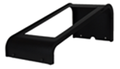
Desktop Stand


Installation
Main Module - IP Flush Master
The IP Flush Master supports Power over Ethernet (PoE, IEEE 802.3 a-f).
If PoE is not available, the IP Station can be connected to a 24 VDC local power supply. See IP Station Installation on how to connect 24VDC.
There are two RJ45 ports on the IP Flush Master station.
- LAN port: for connecting to the network and the AlphaCom XE Audio Server.
- AUX port: for connecting to auxiliary equipment such as a PC or IP Camera.

Handset module
Insert the RJ11 plug of the handset into the lower port of the dual RJ11 ports on the lower left of the station.

Related articles:
- Overview of connectors: IP Station Board Connections and Indications.
- Handset compatibility: IP Flush Master and IP Flush Handset compatibility.
DAK-48 Expansion module
The IP DAK-48 unit expands the IP Flush Master station with an additional 48 Direct Access Keys. Up to two DAK-48 units can be connected to one station. Use the RJ45-RJ45 cable which is coming with the DAK-48 unit. The DAK-48 unit receive its power and data via this cable.
WARNING: A standard patch cable (1:1) must not be used. It might damage the unit!
Installing the IP DAK-48 Unit:
- Disconnect the power from the IP Flush Master station
- Plug one end of the RJ45-RJ45 cable into the RJ45 port on the right of the station (when the station is viewed from the front).
- Plug the other end of the RJ45-RJ45 cable into the left (when the unit is viewed from the front) RJ45 port on the DAK unit.
- Connect the power from the IP Flush Master station

Headset connection
The IP Flush Master station is fit with an RJ11 connector for headset connection. Insert the RJ11 plug of the headset into the upper port of the dual RJ11 ports on the lower left of the station. A regular PC style headset can be used. If the headset is not equipped with an RJ11 connector, an adapter must be made locally.
The headset will automatically be detected when connected, and a headset icon will appear in the top right corner of the display. The microphone and loudspeaker on the IP Flush Master panel will be disabled, and the audio routed to the headset.

For more details and options, see: IP Flush Master and Headset
Gooseneck mounting
- Remove the cover plug from the opening for the microphone on the front panel.
- Thread the microphone cable through the opening, the lock washer and nut.
- Tighten the nut on the microphone’s threaded stud.
- Insert the microphone’s IDC socket into the upper two pins of the 3-pin header (J7) located at the lower left side of the station. The signal wire (white) should be on the top pin while the ground wire (green) should be on the bottom pin.
- Slide the S1 switch (bottom back of station) to EXT to activate the external microphone function.

Station Type
By setting a station to Station Type: CRM in AlphaPro the display layout will change from the standard two line display to a four line display.

The display on the station will instead of showing the date, time and station number and name, only show the date and time in the top line. Line 2 and 3 are used for the queue navigation, and line 4 is used for labelling the navigation keys when there is an entry in the queue.
The CRM station type selection will also turn on the backlight constantly.
Incoming mails (typically Call Requests) to a CRM station will form up a queue in the order they are coming in, where the last mail is at the bottom. All incoming mails have a priority (0-255), and a mail with priority higher than the ones in the queue already will go straight to the top. The four navigation keys below the display can be used to navigate the queue, and will be visible only when there are any entries in the queue.
The default navigation keys for a CRM are (from left to right):
- 7638 = Answer (Answer the highlighted mail by calling back to it)
- 7639 = Next (Go to the next mail in the queue)
- 7632 = Top (Go to the first mail in the queue)
- 7630 = Delete (Delete the highlighted entry)
The navigation keys can be configured using AlphaPro:

LED Control
The IP Flush Master has four DAK keys. In addition the station can be fitted with up to two DAK-48 panels to make a total of 100 DAK keys. of which all have two LED's each.

The two LED's (red and green) can be controlled individually using the IND command in the Event Handler.
Typical events to control LED's:
Call Request
To turn on the red led, flashing fast, in the associated DAK key when a Call Request is received, create this event:

| Event Owner: | The CRM-V station or a group of CRM-V stations | Enter the physical station number or the UDP group number |
| Event type: | 10 - Received mail | |
| Subevent: | N/A | |
| When change to: | ON or OFF | |
| When related to: | All | |
| Action: | IND %1.phy %1.dak(I%2.dir) 1 3 | Replace I%2.dir with I2%.dir* to make it work with DAK keys containing longer strings e.g. "I202 M" |
Outgoing Conversation
To turn on the green led in the associated DAK key when an outgoing call is made, create this event:

| Event Owner: | The CRM-V station or a group of CRM-V stations | Enter the physical station number or the UDP group number |
| Event type: | 08 - Conversation - Outgoing | |
| Subevent: | N/A | |
| When change to: | ON or OFF | |
| When related to: | All | |
| Action: | IND %1.phy %1.dak(I%2.dir) 2 1 | Replace I%2.dir with I2%.dir* to make it work with DAK keys containing longer strings e.g. "I202 M" |
Incoming Conversation
To turn on the green led in the associated DAK key when an incoming call is received, create this event:

| Event Owner: | The CRM-V station or a group of CRM-V stations | Enter the physical station number or the UDP group number |
| Event type: | 07 - Conversation - Incoming | |
| Subevent: | N/A | |
| When change to: | ON or OFF | |
| When related to: | All | |
| Action: | IND %1.phy %1.dak(I%2.dir) 2 1 | Replace I%2.dir with I2%.dir* to make it work with DAK keys containing longer strings e.g. "I202 M" |
Door Status
An input of the IP substation can be connected to a door magnet, providing indication on the DAK panel, showing if the door is open or closed.
Example:
To turn on the red led in the associated DAK key when input 3 of the station is activated, create this event:

| Event Owner: | The Door Station or a group of Door stations | Enter the physical station number or the UDP group number |
| Event type: | 30 - Station DAK key as RCI | |
| Subevent: | 3 | Equal to the IP station input that is used |
| When change to: | ON or OFF | |
| When related to: | All | |
| Action: | tmp 0 "%1.dir" | Temporarily store the station directory number |
| OWN 105 | Set the CRM directory number as owner of the event | |
| IND %1.phy %1.dak(I%tmp(0)) 1 1 |
Station Down
To turn on the red and green led in the associated DAK key when a station is reported faulty, create this event:

| Event Owner: | A group of stations | Use UDP group 8 for all stations |
| Event type: | 13 - Faulty station line | |
| Subevent: | 0 | |
| When change to: | ON or OFF | |
| When related to: | N/A | |
| Action: | tmp 0 "%1.dir" | Temporarily store the station directory number |
| OWN 105 | Set the CRM directory number as owner of the event | |
| IND %1.phy %1.dak(I%tmp(0)) 1 1 | ||
| IND %1.phy %1.dak(I%tmp(0)) 2 1 |
DAK Redirection

Unused DAK tables from other stations must be borrowed to extend the CRM DAK table. CRM's using the same DAK layout can redirect to the same tables.

The DAK key configuration must be performed at the users DAK table to which the original CRM DAK table is pointing:


Call Forwarding
Manual:
- Call Requests are forwarded using the feature code 7870 + destination directory number
- Regular point to point calls are forwarded by using the feature code 71 + destination directory number
- To reset the call forwarding, dial 70.
Automatic: A typical CRM application is to transfer calls and call requests from a local guard to a main guard. In the example below two scenarios are shown:
1: The local guard is leaving his station for a while and transfers all calls and call requests to the main guard (directory number 110) by pressing D1 (DAK 1).
DAK 1 is configured with an event trigger:

When a CRM station presses D1 an event trigger (9534) is dialled triggering an event:

| Event Owner: | The CRM-V station or a group of CRM-V stations | Enter the physical station number or the UDP group number |
| Event type: | 15 - Event Trigger Feature | |
| Subevent: | 0 | |
| When change to: | ON | |
| When related to: | Directory Nnumber: 9534 | |
| Action: | IF %udd(%1.dir) | Toggle function: checks transfer status |
| $TRF L%1.dir "" | Remove call transfer | |
| $SCRT L%1.dir | Remove Call Request transfer | |
| IND %1.dir %1.dak(I%2.dir) 1 1 OFF | Turn off red LED in D1 | |
| LOG "Transfer deactivated from %1.dir %1.nam to Main Guard" | Log the action | |
| WUDD %1.dir 0 | Toggle function: set transfer status to off | |
| STOP | ||
| ENDIF | ||
| $TRF L%1.dir "I110" | Set call transfer to Main Guard | |
| $SCRT L%1.dir L110 | Set Call Request transfer to Main Guard | |
| IND %1.dir %1.dak(I%2.dir) 1 1 ON | Turn on red LED in D1 | |
| LOG "Transfer activated from %1.dir %1.nam to Main Guard" | Log the action | |
| WUDD %1.dir 1 | Toggle function: set transfer status to on |
See also:
Additional Settings
Autosearch
Calls and Call Requests can be forwarded automatically to a predefined receiver if unanswered :


Audio Indication
See: Call Request Notification when Station type is set to CRM
Default Priority level    Arrival notification    Queue notification
-----------------------------------------------------------------------
  0 –  59                 No tone                 Beep every minute
 60 – 119                 Dut-dut-dut tone        Beep every minute
120 – 149                 Dut-dut-dut tone        Urgent Feature Reminder (configurable)
150 – 255                 No tone                 Private ringing tone
To configure the Urgent feature reminder:

To change the default priority levels:
