Difference between revisions of "Display data receiver adjustment procedure for TouchLine stations"
From Zenitel Wiki
(→Necessary equipment to preform the adjustment:) |
|||
| (3 intermediate revisions by 2 users not shown) | |||
| Line 4: | Line 4: | ||
[[Image: 7007 DisplayAdjust.PNG|right|200px|thumb|Component location A100C07844]] | [[Image: 7007 DisplayAdjust.PNG|right|200px|thumb|Component location A100C07844]] | ||
This procedure describes the adjustment of the receiver in the TouchLine display stations based on the Motorola 68HC05 microcontroller. The relevant boards are: | This procedure describes the adjustment of the receiver in the TouchLine display stations based on the Motorola 68HC05 microcontroller. The relevant boards are: | ||
| − | <br | + | <br /> |
# A100C01340, used in the TouchLine 10070013xx, 100703x3xx and the interguard 100707xxxx stations | # A100C01340, used in the TouchLine 10070013xx, 100703x3xx and the interguard 100707xxxx stations | ||
# A100C01425, used in the TouchLine 1007042000, 1007043000 and many custom design flush mounted stations | # A100C01425, used in the TouchLine 1007042000, 1007043000 and many custom design flush mounted stations | ||
# A100C07844, used in the DualDisplay station 1007007000 | # A100C07844, used in the DualDisplay station 1007007000 | ||
| − | <br | + | <br /><br /><br /> |
=== Necessary equipment to preform the adjustment: === | === Necessary equipment to preform the adjustment: === | ||
[[Image: Display data receiver adjustment procedure for CRM-IV2.jpg|left|200px|thumb|Oscilloscope wave form]] | [[Image: Display data receiver adjustment procedure for CRM-IV2.jpg|left|200px|thumb|Oscilloscope wave form]] | ||
- Oscilloscope with 10M ohm probe with insulating transformer on the power supply | - Oscilloscope with 10M ohm probe with insulating transformer on the power supply | ||
| − | <br | + | <br /> |
- An AlphaCom exchange. | - An AlphaCom exchange. | ||
| − | <br | + | <br /> |
- A screwdriver suitable for the potmeter's RP1 and PR2. | - A screwdriver suitable for the potmeter's RP1 and PR2. | ||
| − | <br | + | <br /><br /> |
* - Adjust RP1 and RP2 to approx. 75 kohm | * - Adjust RP1 and RP2 to approx. 75 kohm | ||
* - Connect the oscilloscope probe to pin 11 on the PLL 74HCT4046, This is IC U5 on the A100C01340 and A100C01425, and IC U3 on A100C07844. | * - Connect the oscilloscope probe to pin 11 on the PLL 74HCT4046, This is IC U5 on the A100C01340 and A100C01425, and IC U3 on A100C07844. | ||
| Line 23: | Line 23: | ||
* - Adjust RP1 and RP2 until the waveform it is as shown on the figure, '''''be accurate'''''! | * - Adjust RP1 and RP2 until the waveform it is as shown on the figure, '''''be accurate'''''! | ||
* - Disconnect the board and reconnect after 2-3 seconds. Dial 789. The display should now reset. | * - Disconnect the board and reconnect after 2-3 seconds. Dial 789. The display should now reset. | ||
| − | <br | + | <br /> |
| − | <br | + | <br /> |
| − | <br | + | <br /> |
| − | <br | + | <br /> |
This waveforms are very probe dependent. You have to experience the centre of the tolerance area yourself. Pay special attention to the slopes and the second peek on the curve. | This waveforms are very probe dependent. You have to experience the centre of the tolerance area yourself. Pay special attention to the slopes and the second peek on the curve. | ||
[[Image:Picture3 Good adj of RP2.jpg|thumb|350px|left|Good adjustment]] | [[Image:Picture3 Good adj of RP2.jpg|thumb|350px|left|Good adjustment]] | ||
[[Image:Picture2 Not good adj of RP2.jpg|thumb|350px|left|Bad adjustment]] | [[Image:Picture2 Not good adj of RP2.jpg|thumb|350px|left|Bad adjustment]] | ||
| − | + | ||
| − | |||
| − | |||
[[Category: Station Troubleshooting]] | [[Category: Station Troubleshooting]] | ||
| + | [[Category: Analogue Station - Technical articles]] | ||
Latest revision as of 14:14, 1 November 2016
TouchLine station display data receiver adjustment procedure
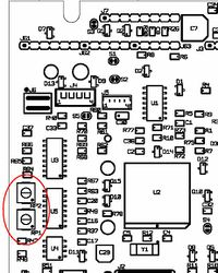
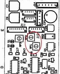
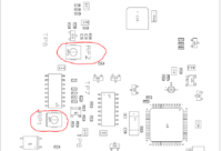
This procedure describes the adjustment of the receiver in the TouchLine display stations based on the Motorola 68HC05 microcontroller. The relevant boards are:
- A100C01340, used in the TouchLine 10070013xx, 100703x3xx and the interguard 100707xxxx stations
- A100C01425, used in the TouchLine 1007042000, 1007043000 and many custom design flush mounted stations
- A100C07844, used in the DualDisplay station 1007007000
Necessary equipment to preform the adjustment:
- Oscilloscope with 10M ohm probe with insulating transformer on the power supply
- An AlphaCom exchange.
- A screwdriver suitable for the potmeter's RP1 and PR2.
- - Adjust RP1 and RP2 to approx. 75 kohm
- - Connect the oscilloscope probe to pin 11 on the PLL 74HCT4046, This is IC U5 on the A100C01340 and A100C01425, and IC U3 on A100C07844.
- - Connect the oscilloscope ground to the B-wire close to the station (not more than 3 meters).
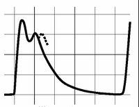
- - Set scope to 1Volt/line vertical division and 2 usec/line horisontal division.
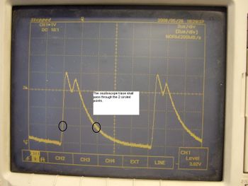
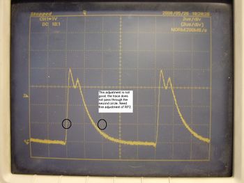
- - Adjust RP1 and RP2 until the waveform it is as shown on the figure, be accurate!
- - Disconnect the board and reconnect after 2-3 seconds. Dial 789. The display should now reset.
This waveforms are very probe dependent. You have to experience the centre of the tolerance area yourself. Pay special attention to the slopes and the second peek on the curve.

