INCA Video Doorstation Board Connectors
From Zenitel Wiki
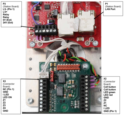
Hardware version 0.1
P1:
- LAN Port
P3:
- 1&2: Loudspeaker 4ohm/2W (already connected)
- 3&4: NO Relay - Potential free relay contact, max 1A/24V
- 5: 0V*
- 6: 24V*
*External power supply, 21-27VDC/0.5A. Attention! Not simultaneously with PoE!
X2:
Button Module 2B:
- GND (ground for illumination)
- I_LED (background illumination (+5V))
- NC
- Z1 (first button) DAK2
- Z2 (second button) DAK3
- GND (reference point buttons)
Call Button (Board version 0.1):
- 7: RT (for red LED (red cable))
- 8: GR (for green LED (green cable))
- 9: SW (closer (button))
- 10: SW (closer (button))
X3:
Button Module 4T:
- NC
- GND (NC)
- I_LED (background illumination)
- LED_ON (grounding for illumination)
- Z1 (1st button) DAK4
- Z2 (2nd button) DAK5
- Z3 (3rd button) DAK6
- Z4 (4th button) DAK7
- "GND" (reference point buttons)
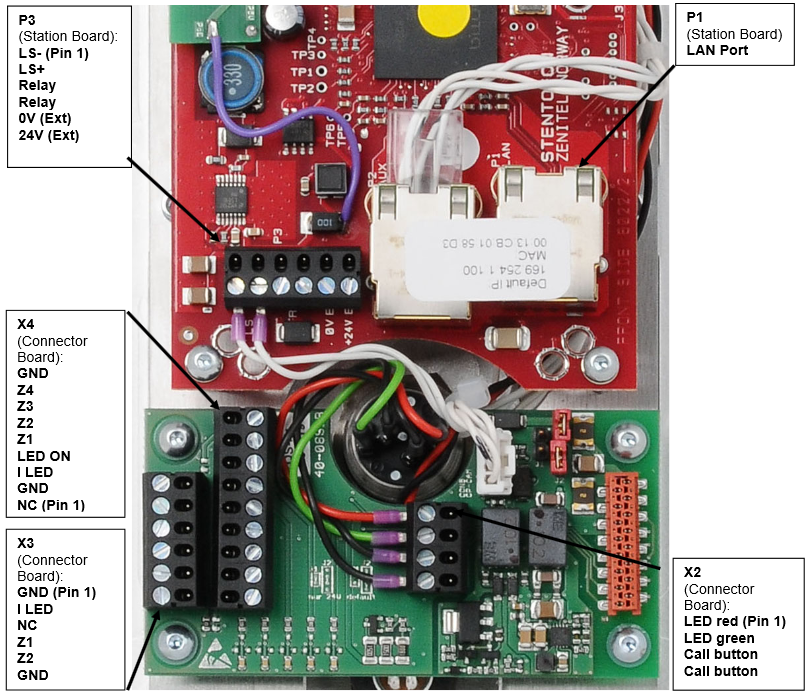
Hardware version 0.2/0.3/1.0
P1:
- LAN Port
P3:
- 1&2: Loudspeaker 4ohm/2W (already connected)
- 3&4: NO Relay - Potential free relay contact, max 1A/24V
- 5: 0V*
- 6: 24V*
*External power supply, 21-27VDC/0.5A. Attention! Not simultaneously with PoE!
X2:
Call Button (Board version 0.2):
- 1: RT (for red LED (red cable))
- 2: GR (for green LED (green cable))
- 3: SW (closer (button))
- 4: SW (closer (button))
X3:
Button Module 2T (Board version 0.2):
- 1: GND (ground for illumination)
- 2: |_LED (background illumination (+5V))
- 3: NC
- 4: Z1 (first button) DAK2
- 5: Z2 (second button) DAK3
- 6: GND (reference point buttons)
X4:
Button Module 4T (Board version 0.2):
- 1: NC
- 2: GND (NC)
- 3: I_LED (background illumination)
- 4: LED_ON (grounding for illumination)
- 5: Z1 (1st button) DAK4
- 6: Z2 (2nd button) DAK5
- 7: Z3 (3rd button) DAK6
- 8: Z4 (4th button) DAK7
- 9: "GND" (reference point buttons)


