IP-LCM Connections
From Zenitel Wiki
Inputs
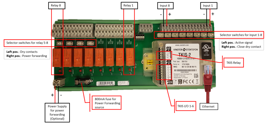
There are 8 inputs. Each of them has a corresponding selector switch, with which one can select between a dry closing contact or an active input.
- Left position: The input requires an active signal, typically 5V, 12V or 24VDC. The input is galvanic isolated with an opto-coupler. Polarity as indicated on the drawing.
- Right position: The input requires a dry contact
Outputs
There are 8 relays, each with two sets of changeover contacts (DPDT). The contact terminals, Normally Open (NO), Normally Closed (NC) and Common (COM), are labeled in the silk print of the PCB.
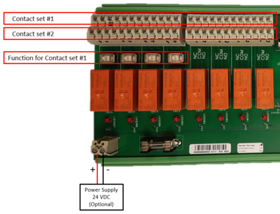
Relay 5 to 8 has a corresponding output selector switch. With this switch one can select if the Contact Set #1 should provide dry contacts, or if it should forward power from the power forwarding connector. Contact Set #2 will always provide dry contacts, regardless of the position of the output selector switch.
- Left position: Contact Set #1 provides dry contacts.
- Right position: Contact Set #1 forwards power from the an external power supply connected to the IP-LCM unit. When the PSU is connected with the polarity as indicated in the drawing above, the "+" will appear on the Com terminal, and the "-" will appear on the NO-terminal when the relay is active. When the relay is in idle, the "-" will appear on the NC-terminal.
Relay contact ratings:
- Outputs: DPDT (Double Pole Double Throw). NO (Normal Open), NC (Normal Closed), COM (Common)
- Switched voltage: < 250VAC Rated (400VAC Max)
- Switched Voltage: < 2000 VA max
- Switching Current: < 8A rated (15A max, 4s)
Indicators
Each output has a LED which indicates if the output is active or not.
See here for for information on the TKIS-2 kit connections


