Difference between revisions of "IP Desktop Master Station with Video Display - Configuration Guide"
From Zenitel Wiki
(→Events Programming) |
|||
| (38 intermediate revisions by 3 users not shown) | |||
| Line 1: | Line 1: | ||
| + | {{obsolete}} | ||
| + | |||
| + | This item is replaced by [[IP Desktop Station with Video Display - 1408001635]] | ||
| + | |||
| + | |||
[[File:IP Desktop with Monitor.PNG|thumb|400px]] | [[File:IP Desktop with Monitor.PNG|thumb|400px]] | ||
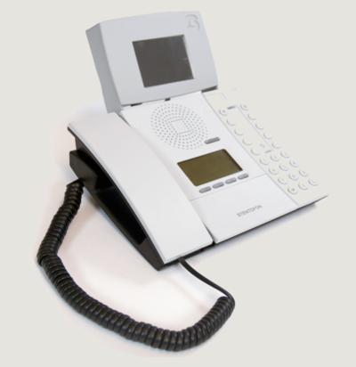
| − | This article provides a detailed step-by step guide to the configuration and programming of the STENTOFON IP Desktop Master Station with Video Display. | + | This article provides a detailed step-by step guide to the configuration and programming of the STENTOFON IP Desktop Master Station with Video Display used together with the IP Video Substation 1038051415. |
This document should provide adequate information for setting up the station and getting it up and running. | This document should provide adequate information for setting up the station and getting it up and running. | ||
| Line 6: | Line 11: | ||
=Introduction= | =Introduction= | ||
All the commands required to use the video display intercom will be described in this document. The following IP addresses will be used throughout the document: | All the commands required to use the video display intercom will be described in this document. The following IP addresses will be used throughout the document: | ||
| − | *Video Display on Master Station IP address = '''192.168. | + | *Video Display on Master Station IP address = '''192.168.1.24''' |
| − | *Master Station IP address = '''192.168. | + | *Master Station IP address = '''192.168.1.23''' |
*AlphaCom IP address = '''192.168.1.5''' | *AlphaCom IP address = '''192.168.1.5''' | ||
| − | *Video Camera on Substation IP address = '''192.168. | + | *Video Camera on Substation IP address = '''192.168.1.12''' |
The video display does not support an Ethernet cable from a PoE port. Power for the video display can only be obtained from an external power supply (available from Zenitel). | The video display does not support an Ethernet cable from a PoE port. Power for the video display can only be obtained from an external power supply (available from Zenitel). | ||
| Line 15: | Line 20: | ||
==Hardware Architecture== | ==Hardware Architecture== | ||
| − | [[File:IP | + | [[File:IP-VideoScetch1.png|thumb|300px]] |
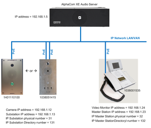
The intercom system architecture including video display is based on the following equipment: | The intercom system architecture including video display is based on the following equipment: | ||
*AlphaCom server (XE1/XE20/XE26) | *AlphaCom server (XE1/XE20/XE26) | ||
| − | *IP Master Station with video display (item no. 1038001535) | + | *IP Master Station with video display (item no. 1038001535/1038000535) |
| − | *IP Substation with video camera (item no. 1038051415) | + | *IP Video Substation with video camera (item no. 1038051415) |
| + | *IP Video Door Station with camera (item no. 1401110100) | ||
A simplified diagram of the system configuration is shown to the right: | A simplified diagram of the system configuration is shown to the right: | ||
<br style="clear:both;" /> | <br style="clear:both;" /> | ||
| Line 37: | Line 43: | ||
*Video Codec: '''MPEG-2 at 800 kbps''' | *Video Codec: '''MPEG-2 at 800 kbps''' | ||
| − | ===Powering Up the Video Display | + | ===Powering Up the Video Display=== |
The circuit board must be powered with an external 12 VDC, 1A power supply. No protection is provided on the board. | The circuit board must be powered with an external 12 VDC, 1A power supply. No protection is provided on the board. | ||
'''''NOTE: Do not use a PoE switch port as a power source.''''' | '''''NOTE: Do not use a PoE switch port as a power source.''''' | ||
| Line 57: | Line 63: | ||
[[File:IP Desktop with Monitor 3.PNG|thumb|300px]] | [[File:IP Desktop with Monitor 3.PNG|thumb|300px]] | ||
Run the following command: | Run the following command: | ||
| − | ::'''telnet 192.168. | + | ::'''telnet 192.168.1.24''' |
| + | |||
| + | or use [[Downloads#Useful_Tools|Putty]]. | ||
| + | |||
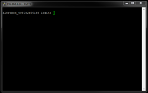
If the connection is successful, the image to the right is displayed: | If the connection is successful, the image to the right is displayed: | ||
| Line 84: | Line 93: | ||
To change the IP address of the video display, you must change the value of the variable '''ipaddr''' e.g.: | To change the IP address of the video display, you must change the value of the variable '''ipaddr''' e.g.: | ||
| − | :'''fw_setenv ipaddr 192.168. | + | :'''fw_setenv ipaddr 192.168.1.24''' |
The operation is completed when '''Done''' is displayed. | The operation is completed when '''Done''' is displayed. | ||
| Line 99: | Line 108: | ||
To ensure that the video display is able to receive a video stream from the network, the following command has to be run: | To ensure that the video display is able to receive a video stream from the network, the following command has to be run: | ||
:'''mplayer -demuxer lavf''' | :'''mplayer -demuxer lavf''' | ||
| − | The following is an example command to receive the stream from a video camera with '''IP address: 192.168. | + | The following is an example command to receive the stream from a video camera with '''IP address: 192.168.1.12''': |
| − | :'''mplayer -demuxer lavf http://192.168. | + | :'''mplayer -demuxer lavf http://192.168.1.12/mjpg/video.mjpg''' |
The video stream should now be displayed on the video display on the master station. | The video stream should now be displayed on the video display on the master station. | ||
| Line 147: | Line 156: | ||
=Video Camera Configuration= | =Video Camera Configuration= | ||
| − | The master station video display only | + | The master station video display supports only the AXIS Protocol. The video camera setup is carried out from the camera web interface. |
| + | |||
| + | ==IP Video Substation 1038051415== | ||
| + | Camera Login: | ||
| + | Username: '''root''' | ||
| + | Password: '''zenitel''' | ||
To assign the IP address of the video camera on the substation: | To assign the IP address of the video camera on the substation: | ||
| Line 153: | Line 167: | ||
*Select '''Setup > Basic Setup > TCP/IP''' | *Select '''Setup > Basic Setup > TCP/IP''' | ||
:1. Select '''Use the following IP address''' and enter values in the fields for IP addresses | :1. Select '''Use the following IP address''' and enter values in the fields for IP addresses | ||
| − | ::- in our example, the video camera has IP address '''192.168. | + | ::- in our example, the video camera has IP address '''192.168.1.12''' |
:2. Validate by clicking '''Save''' | :2. Validate by clicking '''Save''' | ||
<br style="clear:both;" /> | <br style="clear:both;" /> | ||
| Line 166: | Line 180: | ||
*Select '''Setup > Basic Setup > Video Stream''' | *Select '''Setup > Basic Setup > Video Stream''' | ||
:1. For '''Resolution''', select '''CIF (320x240)''' from the scroll-down box. | :1. For '''Resolution''', select '''CIF (320x240)''' from the scroll-down box. | ||
| − | :2. Validate by clicking '''Save''' | + | :2. For '''Maximum Frame Rate''', select '''Limited to''', and set '''18'''. |
| + | :3. Validate by clicking '''Save''' | ||
<br style="clear:both;" /> | <br style="clear:both;" /> | ||
| Line 173: | Line 188: | ||
*Click '''Restart''' | *Click '''Restart''' | ||
<br style="clear:both;" /> | <br style="clear:both;" /> | ||
| + | |||
| + | ==IP Video Door Station 1401110100== | ||
| + | Please see article [[IP Video Door Station]] for details. | ||
=AlphaCom Server Settings= | =AlphaCom Server Settings= | ||
| Line 228: | Line 246: | ||
===Video Display IP Link Configuration=== | ===Video Display IP Link Configuration=== | ||
| − | [[File:IP Desktop with Monitor 18.PNG|thumb| | + | [[File:IP Desktop with Monitor 18.PNG|thumb|left|500px|the]] |
| + | <br style="clear:both;" /> | ||
The communication between the AlphaCom server and the video display is created through a TCP/IP link. | The communication between the AlphaCom server and the video display is created through a TCP/IP link. | ||
*Click the '''Exchange & System''' icon | *Click the '''Exchange & System''' icon | ||
| Line 234: | Line 253: | ||
*Highlight an EDIO port | *Highlight an EDIO port | ||
::- in our example, the port '''EDIO 1''' | ::- in our example, the port '''EDIO 1''' | ||
| − | *Enter values in the fields as shown | + | *Enter values in the fields as shown to the right: |
| − | + | ||
===Events Programming=== | ===Events Programming=== | ||
| − | + | ||
A video stream can be activated with any type of event in the list via AlphaPro. | A video stream can be activated with any type of event in the list via AlphaPro. | ||
| − | To enable a video stream to a monitor, you should use the following | + | To enable a video stream to a monitor, you should use the following event: |
| − | :'''EDO 1 | + | [[File:IP Desktop with Monitor 19.PNG|thumb|left|500px|Event to activate video stream]] |
| − | + | <br style="clear:both;" /> | |
| + | |||
| + | Action command details: | ||
| + | '''EDO 1 "GET /cmd/CAMCONNECT.php?BOX=192.168.1.24&CAM=192.168.1.12 HTTP/1.1\r\nHost: 127.0.0.1\r\nConnection: Keep-Alive\r\n"''' | ||
| + | '''EDO 1 "Accept: */*\r\n\r\n"''' | ||
| + | |||
where: | where: | ||
:'''BOX''' is followed by the IP address of the video display | :'''BOX''' is followed by the IP address of the video display | ||
:'''CAM''' is followed by the IP address of the video camera | :'''CAM''' is followed by the IP address of the video camera | ||
| − | In our example, '''Directory Number 6998''' will enable the video stream of the camera at '''IP address 192.168. | + | In our example, '''Directory Number 6998''' will enable the video stream of the camera at '''IP address 192.168.1.12''' to video display at '''IP address 192.168.1.24'''. |
| + | |||
| + | |||
| + | |||
| + | If you want to disable the video stream on the video display, the following event must be used: | ||
| + | [[File:IP Desktop with Monitor 20.PNG|thumb|left|500px|Event to deactivate video stream]] | ||
<br style="clear:both;" /> | <br style="clear:both;" /> | ||
| + | Action command details: | ||
| + | '''EDO 1 "GET /cmd/CAMDISCONNECT.php?BOX=192.168.1.24 HTTP/1.1\r\nHost: 127.0.0.1\r\nConnection: Keep-Alive\r\n"''' | ||
| + | '''EDO 1 "Accept: */*\r\n\r\n"''' | ||
| + | where: | ||
| + | :'''BOX''' is followed by the IP address of the video display. | ||
| + | In our example, the '''Directory Number 6999''' will disable the video stream of the video display at IP address 192.168.1.24. | ||
| − | |||
| − | |||
| − | |||
| − | |||
| − | |||
| − | |||
| − | |||
| − | |||
''NOTE! Make sure there is no line shifts in the commands.'' | ''NOTE! Make sure there is no line shifts in the commands.'' | ||
| − | |||
| − | |||
| − | |||
| + | =Related Articles= | ||
| + | *[[IP Desktop Master Station with Video Display - Practical Examples]] | ||
| + | *[[IP SubStation with Video and Inductive Loop]] | ||
| − | [[Category: | + | [[Category: Discontinued Stations]] |
| − | |||
Latest revision as of 13:55, 14 June 2018
This item is replaced by IP Desktop Station with Video Display - 1408001635
This article provides a detailed step-by step guide to the configuration and programming of the STENTOFON IP Desktop Master Station with Video Display used together with the IP Video Substation 1038051415.
This document should provide adequate information for setting up the station and getting it up and running.
Contents
Introduction
All the commands required to use the video display intercom will be described in this document. The following IP addresses will be used throughout the document:
- Video Display on Master Station IP address = 192.168.1.24
- Master Station IP address = 192.168.1.23
- AlphaCom IP address = 192.168.1.5
- Video Camera on Substation IP address = 192.168.1.12
The video display does not support an Ethernet cable from a PoE port. Power for the video display can only be obtained from an external power supply (available from Zenitel).
Technical personnel responsible for video display programming should have some working experience with STENTOFON software/interface such as AlphaPro and AlphaWeb.
Hardware Architecture
The intercom system architecture including video display is based on the following equipment:
- AlphaCom server (XE1/XE20/XE26)
- IP Master Station with video display (item no. 1038001535/1038000535)
- IP Video Substation with video camera (item no. 1038051415)
- IP Video Door Station with camera (item no. 1401110100)
A simplified diagram of the system configuration is shown to the right:
Functional Architecture
When someone initiates a call from the substation with video camera, the AlphaCom server sends a request to the AXIS camera which broadcasts its video stream on the LAN/VLAN. The command is generated from two scripts programmed in AlphaCom (one script for video stream connection to the video display and one script to disable the video stream from the video display).
This video stream is recovered by the AlphaCom server which transcodes the stream to a 320 x 240 pixel format so that it can be displayed on the video display.
Prerequisites
Video Stream
The video stream is read from the video display on a web server specified by the AlphaCom server. Hence, there is no recommended size or duration for the source file. The image resolution must be 320x240 pixels. Other resolutions are not supported.
Recommendations:
- File extension: mpg
- Resolution : 320x240 pixels
- Video Codec: MPEG-2 at 800 kbps
Powering Up the Video Display
The circuit board must be powered with an external 12 VDC, 1A power supply. No protection is provided on the board.
NOTE: Do not use a PoE switch port as a power source.
Video Display Settings
To set up the video display, the user must connect an Ethernet network cable to the master station. The user interface is accessible via a Telnet connection. The setup procedure is as described in the following sections.
Video Display Connection
Open the Command Prompt window on the PC by doing the following:
In Windows XP
- 1. Click Start > Run
- 2. Type cmd and press Enter
In Windows 7
- 1. Click Start
- 2. Type cmd and press Enter
Run the following command:
- telnet 192.168.1.24
or use Putty.
If the connection is successful, the image to the right is displayed:
Log in with the following user account settings:
- Login: root
- Password: aivonis
After logging in, you can start the configuration procedure.
Video Display Configuration
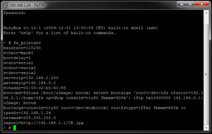
To display the video display configuration, run the following command:
- fw_printenv
The configuration settings of the video display will be displayed like the image on the right:
The information related to the IP configuration of the video display is:
- ipaddr - Video display IP address
- gatewayip - Video display gateway IP address
- ethaddr - Video display MAC address
- imgurl - Address of the server where the standby image is located
Changing Video Display IP Configuration
The variables described below are used for changing the IP configuration of the video display.
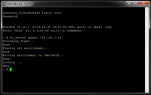
To change the IP address of the video display, you must change the value of the variable ipaddr e.g.:
- fw_setenv ipaddr 192.168.1.24
The operation is completed when Done is displayed.
To change the video display gateway address, change the value of the variable gatewayip e.g.:
- fw_setenv gatewayip 192.168.0.2
To change the net mask on the video display, change the value of the variable netmask e.g.:
- fw_setenv netmask 255.255.255.0
Test Camera Video Stream
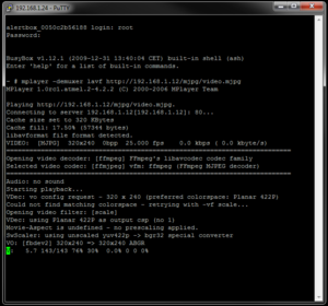
To ensure that the video display is able to receive a video stream from the network, the following command has to be run:
- mplayer -demuxer lavf
The following is an example command to receive the stream from a video camera with IP address: 192.168.1.12:
- mplayer -demuxer lavf http://192.168.1.12/mjpg/video.mjpg
The video stream should now be displayed on the video display on the master station.
The above window appears when you get a good reading from the stream of the video camera.
To stop the streaming, press CTRL + C.
Modify Standby Logo on Video Display
Prerequisites
Save the image/logo to be displayed under Scripts in AlphaWeb.
The new image/logo will be displayed when there is communication between the video display and the AlphaCom server. Otherwise, the default STENTOFON logo is displayed.
The image/logo must have the following features:
- Image resolution: 380x240 pixels
- Format: jpg
Image/Logo Update
The image can be updated by using the variable imgurl available on the master station. This variable contains the address of the server where the image is saved (in this case, it is the IP address of the AlphaCom server).
To insert a new image:
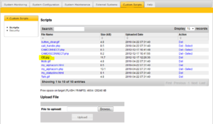
- Log into AlphaCom via AlphaWeb
- Select the Custom Scripts tab and log in to your PC with the following access code:
- - User name: scripter
- - Password: alphascript
- Click Browse and navigate to the folder where the image CE.jpg is located
- Click Upload
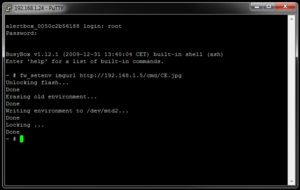
If you wish to confirm the image change, run the following command:
- fw_setenv imgurl http://192.168.1.5/cmd/CE.jpg
192.168.1.5 is the address of the AlphaCom server that contains the registered logo/image CE.jpg.
The image modification will take effect after the video display is rebooted, when the new logo has been downloaded.
To reboot, run the following command:
- reboot
The video display will then restart and the new logo will appear.
Video Camera Configuration
The master station video display supports only the AXIS Protocol. The video camera setup is carried out from the camera web interface.
IP Video Substation 1038051415
Camera Login:
Username: root
Password: zenitel
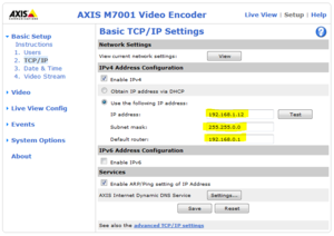
To assign the IP address of the video camera on the substation:
- Select Setup > Basic Setup > TCP/IP
- 1. Select Use the following IP address and enter values in the fields for IP addresses
- - in our example, the video camera has IP address 192.168.1.12
- 2. Validate by clicking Save
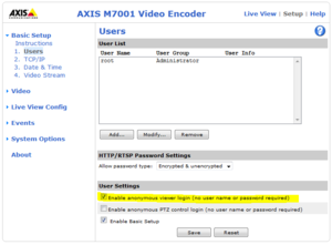
- Select Setup > Basic Setup > Users
- 1. Check the box for Enable anonymous viewer login (no user name or password required)
- 2. Validate by clicking Save
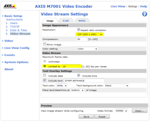
- Select Setup > Basic Setup > Video Stream
- 1. For Resolution, select CIF (320x240) from the scroll-down box.
- 2. For Maximum Frame Rate, select Limited to, and set 18.
- 3. Validate by clicking Save
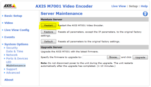
- Select Setup > System Options > Maintenance
- Click Restart
IP Video Door Station 1401110100
Please see article IP Video Door Station for details.
AlphaCom Server Settings
The AlphaCom system is configured using the AlphaPro programming tool and the AlphaWeb interface through the AlphaCom server.
AlphaWeb
Log into the AlphaCom server via AlphaWeb on a browser.
The AlphaCom server will be connected to the video display via a TCP/IP link through the Ethernet network. The AlphaWeb interface will allow Ethernet ports eth0 and eth1 to be configured.
IP Network Configuration
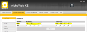
To set the IP address and AlphaCom subnet mask:
- Select the System Configuration tab
- Select Interfaces and enter values in the fields as indicated below
- - in our example, the port eth0 is connected using TCP/IP and the AlphaCom IP address is 192.168.1.5 with subnet mask 255.255.0.0
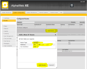
To set the Gateway IP Address (if required):
- Select the System Configuration tab
- Select Routes and click Add Route
- Enter values in the Gateway field as indicated below
- - in our example, the router gateway IP address is 192.168.1.1
The video stream control is obtained through URL commands via http.
The http port must be enabled on the Ethernet port connected to the video display (in this example, port Eth0).
To enable the http port:
- Select the System Configuration tab
- Select Filters and check the box under Eth0 for HTTP
Scripts Inserts
The command to enable and disable the video stream from the camera to the video display is carried out with two scripts:
- Connect the video stream with the script CAMCONNECT.php
- Disconnect the video stream with the script CAMDISCONNECT.php
These scripts can be downloaded from the Downloads section.
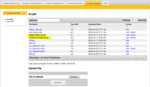
To insert scripts:
- Select the Custom Scripts tab and enter:
- - User name: scripter
- - Password: alphascript
To upload a script file:
- Click Browse and navigate to the folder where the script files CAMCONNECT.php and CAMDISCONNECT.php are located
- Click Upload for each script file
AlphaPro
The activation of a video stream to a video display is created through an IP connection from an event selected via AlphaPro.
Video Display IP Link Configuration
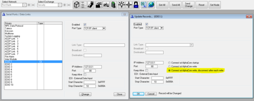
The communication between the AlphaCom server and the video display is created through a TCP/IP link.
- Click the Exchange & System icon
- Click Serial Ports
- Highlight an EDIO port
- - in our example, the port EDIO 1
- Enter values in the fields as shown to the right:
Events Programming
A video stream can be activated with any type of event in the list via AlphaPro.
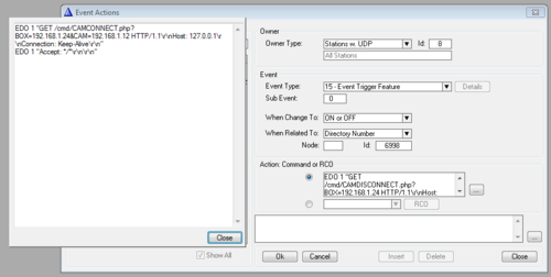
To enable a video stream to a monitor, you should use the following event:
Action command details:
EDO 1 "GET /cmd/CAMCONNECT.php?BOX=192.168.1.24&CAM=192.168.1.12 HTTP/1.1\r\nHost: 127.0.0.1\r\nConnection: Keep-Alive\r\n"
EDO 1 "Accept: */*\r\n\r\n"
where:
- BOX is followed by the IP address of the video display
- CAM is followed by the IP address of the video camera
In our example, Directory Number 6998 will enable the video stream of the camera at IP address 192.168.1.12 to video display at IP address 192.168.1.24.
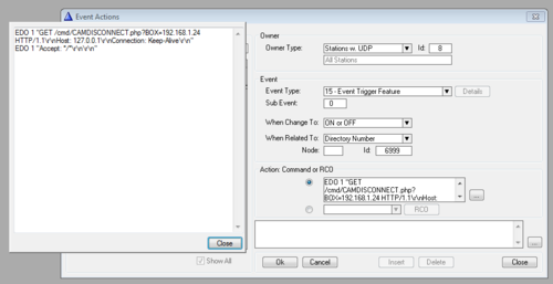
If you want to disable the video stream on the video display, the following event must be used:
Action command details:
EDO 1 "GET /cmd/CAMDISCONNECT.php?BOX=192.168.1.24 HTTP/1.1\r\nHost: 127.0.0.1\r\nConnection: Keep-Alive\r\n"
EDO 1 "Accept: */*\r\n\r\n"
where:
- BOX is followed by the IP address of the video display.
In our example, the Directory Number 6999 will disable the video stream of the video display at IP address 192.168.1.24.
NOTE! Make sure there is no line shifts in the commands.


