Difference between revisions of "IP Flush Master -V2 Board Connectors"
From Zenitel Wiki
| (50 intermediate revisions by 3 users not shown) | |||
| Line 1: | Line 1: | ||
{{AEIS}}This chapter gives details about connections and indications for: | {{AEIS}}This chapter gives details about connections and indications for: | ||
| − | |||
| − | [[ | + | *[[IP Flush Master -V2]] |
| + | *[[IP-CROR]] | ||
| + | *[[IP Master Station Kit - 1008493000|IP Master Station Kit -V2]] | ||
| + | <br clear=all/> | ||
| + | __NOTOC__ | ||
| − | + | [[File:IPFlushDrawingwith numbers.png|thumb|left|800px]] | |
| − | < | + | <br clear=all/> |
| − | + | {| border="1" } | |
| + | | align="center" style="background:#ffd400;" |'''Item''' | ||
| + | | align="center" style="background:#ffd400;" |'''Description''' | ||
| + | | align="center" style="background:#ffd400;" |'''''Comment''''' | ||
| + | |- | ||
| + | | P3 || Pluggable screw connector || * 1/2 = Connection to internal loudspeaker (8ohm) <br> * 3/4 = Relay <br> * 5/6 = Not in use | ||
| + | |- | ||
| + | | P4 || Pluggable screw connector || * 1/2/ = Input 1-3 <br> * 4 = Common <br> * 5/6 = Station LED (5=A, 6=C) | ||
| + | |- | ||
| + | | J1 || [[IP Flush Master DAK-48 Module|D48 Expansion Module]] || RJ45 Connector to connect D48 modules, via I2C bus. | ||
| + | |- | ||
| + | | P14 || External loudspeaker || 3-pin screw connector for 8 ohm loudspeaker (max 5W). Operates in parallel with internal speaker. | ||
| + | |- | ||
| + | | J3 || 5VDC || 5 volt DC output | ||
| + | |- | ||
| + | | P1 & P2 || LAN Port || 10/100Mbps RJ-45 port for Ethernet connection. | ||
| + | |- | ||
| + | | P600 || External Power Supply || 2-pin screw connector for connecting external 24-48VDC power supply. Max 300mA. | ||
| + | |- | ||
| + | | J5 || Display || 20-pin ZIF connector for LCD display. Separate display panels are available as a kit of 5 units (order no. 1008099000). | ||
| + | |- | ||
| + | | P5 || Keyboard || Solderpoints See details further down. | ||
| + | |- | ||
| + | | J4 || Keyboard || 18 pin ZIF connector. See details further down. | ||
| + | |- | ||
| + | | J8 || Handset/Headset || Dual RJ11 for Handset and Headset. See details further down. | ||
| + | |- | ||
| + | | J7 || Gooseneck || 3-pin header for connecting gooseneck microphone. 1 is +, 2 is - and 3 is GND. | ||
| + | |- | ||
| + | | S1 || Microphone selector || Slide switch to select internal microphone (int) or gooseneck microphone (ext) | ||
| + | |- | ||
| + | | J10 || Microphone || Internal microphone. Pin 1 is + and 2 is -. | ||
| + | |- | ||
| + | |} | ||
| − | + | ==Inputs== | |
| − | + | {{Note| | |
| − | + | * ''When "Station Type" is set as '''Master station''' in AlphaPro, the inputs are mapped as DAK '''11, 12''' and '''13'''.'' | |
| − | + | * ''When the "Station Type" is set as '''CRM''' in AlphaPro, the inputs are mapped as '''251, 252''' and '''253'''.'' | |
| − | + | }} | |
| − | |||
| − | |||
| − | == | + | ==Keyboard matrix== |
| − | + | [[File:IP-StationWeb Keyboard Matrix Standard.PNG|left|thumb|300px|P5 or J4 keyboard matrix]] | |
| − | [[File:IP | ||
<br style="clear:both;" /> | <br style="clear:both;" /> | ||
| − | |||
| − | |||
| − | |||
| − | |||
| − | |||
| − | + | '''P5 pinnings:''' | |
| − | + | [[File:IPFlushMasterPCB P5 new.png|left|thumb|300px|Pinout on P5]] | |
| − | [[File: | ||
<br style="clear:both;" /> | <br style="clear:both;" /> | ||
| − | |||
| − | |||
| − | |||
| − | |||
| − | |||
| − | |||
| − | |||
| − | |||
| − | |||
| − | |||
| − | |||
| − | |||
| + | '''J4 connector''' | ||
In software you can choose between four different matrix types, see [[Keyboard Settings]]. | In software you can choose between four different matrix types, see [[Keyboard Settings]]. | ||
| − | |||
| − | |||
| − | |||
| − | |||
| − | |||
18-pin ZIF-connector for keyboard. The keyboard may have up to 10 dialling keys, M and C keys, 10 DAK keys, 10 soft keys, volume up/down and light dim up/down keys connected in a matrix according to the drawing. | 18-pin ZIF-connector for keyboard. The keyboard may have up to 10 dialling keys, M and C keys, 10 DAK keys, 10 soft keys, volume up/down and light dim up/down keys connected in a matrix according to the drawing. | ||
| Line 55: | Line 66: | ||
<br style="clear:both;" /> | <br style="clear:both;" /> | ||
| − | + | *J4/10 DAK1 Green LED | |
| − | + | *J4/11 DAK1 Red LED | |
| − | + | *J4/12 DAK2 Green LED | |
| − | + | *J4/13 DAK2 Red LED | |
| − | + | *J4/14 DAK3 Green LED | |
| − | + | *J4/15 DAK3 Red LED | |
| − | + | *J4/16 DAK4 Green LED | |
| − | + | *J4/17 DAK4 Red LED | |
| − | *J4/10 DAK1 Green LED | ||
| − | *J4/11 DAK1 Red LED | ||
| − | *J4/12 DAK2 Green LED | ||
| − | *J4/13 DAK2 Red LED | ||
| − | *J4/14 DAK3 Green LED | ||
| − | *J4/15 DAK3 Red LED | ||
| − | *J4/16 DAK4 Green LED | ||
| − | *J4/17 DAK4 Red LED | ||
*J4/18 Common +3.3 V | *J4/18 Common +3.3 V | ||
| − | |||
| − | + | ==Handset and Headset== | |
| − | + | ''Handset can optionally be connected via J11, J12 and J13.'' | |
| − | + | '''J11, J12 & J13 - Handset''' | |
| − | |||
| − | |||
| − | + | Pin header for handset connection. Same as J8 pin 1 - 6. | |
| − | + | [[File:IPFlushMasterPCB J11-13.png|left|thumb|400px|J11, J12, J13]] | |
| − | [[File: | ||
<br style="clear:both;" /> | <br style="clear:both;" /> | ||
| − | |||
| − | |||
| − | |||
| − | |||
| − | |||
| − | |||
| − | |||
| − | |||
| − | + | *J11 Pin 1 Spk+ | |
| − | + | *J11 Pin 2 Spk- | |
| − | + | *J12 Pin 1 Mic+ | |
| − | + | *J12 Pin 2 Mic- | |
| − | *Pin 1 | + | *J13 Pin 1 OFFHOOK |
| − | *Pin 2 | + | *J13 Pin 2 GND |
| − | *Pin | ||
| − | |||
| − | |||
| − | |||
<u>'''Handset:'''</u> | <u>'''Handset:'''</u> | ||
[[File:IP Master Board 7.PNG|left|thumb|200px|J8]] | [[File:IP Master Board 7.PNG|left|thumb|200px|J8]] | ||
<br style="clear:both;" /> | <br style="clear:both;" /> | ||
| − | *Pin 1 Mic+ | + | |
| − | *Pin 2 Spk+ | + | *Pin 1 Mic+ |
| − | *Pin 3 Spk- (0 V) | + | *Pin 2 Spk+ |
| − | *Pin 4 Mic- | + | *Pin 3 Spk- (0 V) |
| − | *Pin 5 Hook-switch (must be connected to pin 6 via a switch) | + | *Pin 4 Mic- |
| + | *Pin 5 Hook-switch (must be connected to pin 6 via a switch) | ||
*Pin 6 Hook-switch Ground | *Pin 6 Hook-switch Ground | ||
| Line 118: | Line 106: | ||
[[File:IP Master Board 8.PNG|left|thumb|200px|J8]] | [[File:IP Master Board 8.PNG|left|thumb|200px|J8]] | ||
<br style="clear:both;" /> | <br style="clear:both;" /> | ||
| − | *Pin 7 Mic+ | + | |
| − | *Pin 8 Spk+ | + | *Pin 7 Mic+ |
| − | *Pin 9 Spk- | + | *Pin 8 Spk+ |
| − | *Pin 10 Mic- | + | *Pin 9 Spk- |
| − | *Pin 11 PTT Ground | + | *Pin 10 Mic- |
| + | *Pin 11 PTT Ground | ||
*Pin 12 PTT (Not currently supported by SW) | *Pin 12 PTT (Not currently supported by SW) | ||
| − | + | {{Note| | |
| − | + | Relay switching capacity: Max. 60 watt (Max voltage: 250VAC/220VDC. Max current: 2A) | |
| − | + | }} | |
| − | <br | + | <br clear=all/> |
| − | + | ||
| − | |||
| − | |||
| − | |||
| − | |||
| − | |||
| − | + | [[Category: Turbine Connections]] | |
| − | |||
| − | [[ | ||
| − | |||
| − | |||
| − | |||
| − | |||
| − | |||
| − | |||
| − | |||
| − | |||
| − | |||
| − | |||
| − | |||
| − | |||
| − | |||
| − | |||
| − | |||
| − | |||
| − | |||
| − | |||
Latest revision as of 15:13, 23 June 2023
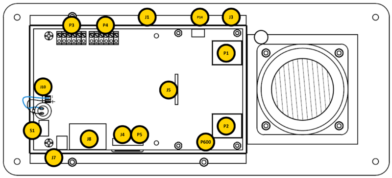
This chapter gives details about connections and indications for:
| Item | Description | Comment |
| P3 | Pluggable screw connector | * 1/2 = Connection to internal loudspeaker (8ohm) * 3/4 = Relay * 5/6 = Not in use |
| P4 | Pluggable screw connector | * 1/2/ = Input 1-3 * 4 = Common * 5/6 = Station LED (5=A, 6=C) |
| J1 | D48 Expansion Module | RJ45 Connector to connect D48 modules, via I2C bus. |
| P14 | External loudspeaker | 3-pin screw connector for 8 ohm loudspeaker (max 5W). Operates in parallel with internal speaker. |
| J3 | 5VDC | 5 volt DC output |
| P1 & P2 | LAN Port | 10/100Mbps RJ-45 port for Ethernet connection. |
| P600 | External Power Supply | 2-pin screw connector for connecting external 24-48VDC power supply. Max 300mA. |
| J5 | Display | 20-pin ZIF connector for LCD display. Separate display panels are available as a kit of 5 units (order no. 1008099000). |
| P5 | Keyboard | Solderpoints See details further down. |
| J4 | Keyboard | 18 pin ZIF connector. See details further down. |
| J8 | Handset/Headset | Dual RJ11 for Handset and Headset. See details further down. |
| J7 | Gooseneck | 3-pin header for connecting gooseneck microphone. 1 is +, 2 is - and 3 is GND. |
| S1 | Microphone selector | Slide switch to select internal microphone (int) or gooseneck microphone (ext) |
| J10 | Microphone | Internal microphone. Pin 1 is + and 2 is -. |
Inputs

|
|
Keyboard matrix
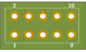
P5 pinnings:
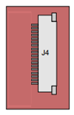
J4 connector In software you can choose between four different matrix types, see Keyboard Settings.
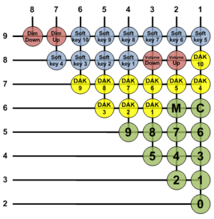
18-pin ZIF-connector for keyboard. The keyboard may have up to 10 dialling keys, M and C keys, 10 DAK keys, 10 soft keys, volume up/down and light dim up/down keys connected in a matrix according to the drawing.
- J4/10 DAK1 Green LED
- J4/11 DAK1 Red LED
- J4/12 DAK2 Green LED
- J4/13 DAK2 Red LED
- J4/14 DAK3 Green LED
- J4/15 DAK3 Red LED
- J4/16 DAK4 Green LED
- J4/17 DAK4 Red LED
- J4/18 Common +3.3 V
Handset and Headset
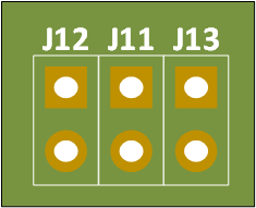
Handset can optionally be connected via J11, J12 and J13.
J11, J12 & J13 - Handset
Pin header for handset connection. Same as J8 pin 1 - 6.
- J11 Pin 1 Spk+
- J11 Pin 2 Spk-
- J12 Pin 1 Mic+
- J12 Pin 2 Mic-
- J13 Pin 1 OFFHOOK
- J13 Pin 2 GND
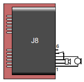
Handset:
- Pin 1 Mic+
- Pin 2 Spk+
- Pin 3 Spk- (0 V)
- Pin 4 Mic-
- Pin 5 Hook-switch (must be connected to pin 6 via a switch)
- Pin 6 Hook-switch Ground
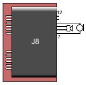
Headset:
- Pin 7 Mic+
- Pin 8 Spk+
- Pin 9 Spk-
- Pin 10 Mic-
- Pin 11 PTT Ground
- Pin 12 PTT (Not currently supported by SW)


