Difference between revisions of "TFIX Connections"
From Zenitel Wiki
| Line 3: | Line 3: | ||
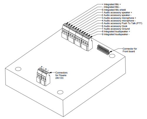
All connections are made on the main board inside the enclosure of the Turbine Ex station. | All connections are made on the main board inside the enclosure of the Turbine Ex station. | ||
| − | === | + | ===Connections=== |
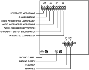
The blue connector is marked +, -, S, and numbers 1 to 9. These should be utilized as follows: | The blue connector is marked +, -, S, and numbers 1 to 9. These should be utilized as follows: | ||
{| class="wikitable" | {| class="wikitable" | ||
Revision as of 18:01, 2 January 2017
All connections are made on the main board inside the enclosure of the Turbine Ex station.
Connections
The blue connector is marked +, -, S, and numbers 1 to 9. These should be utilized as follows:
| J13 | + | Integrated Mic + |
| - | Integrated Mic - | |
| S | Chassis ground | |
| J6 | 1 | Audio accessory speaker + |
| 2 | Audio accessory speaker - | |
| 3 | Audio accessory microphone mic + | |
| J7 | 4 | Audio accessory microphone mic - |
| 5 | Audio accessory Push To Talk (PTT) | |
| 6 | Audio accessory Hook | |
| J9 | 7 | Audio accessory Ground PTT/Hook |
| 8 | Loudspeaker + | |
| 9 | Loudspeaker - |
Flowire connection
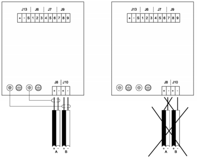
The TFIX station features two Flowire connectors. Power and signal redundancy can be achieved by utilizing both Flowire connectors in an A-B system configuration.
Do not connect more than 9 Ex Products to each central Flowire Converter.
Only use one of the Flowire connectors on each Ex product for each central Flowire Converter.
Load sharing power supply must be used for redundant cabling solutions.
The main board receives both power and Ethernet signals through two wires. You can connect either
A or B for connection to the rest of the system, or both A and B, each to a separate server,
in order to achieve redundancy.


