Difference between revisions of "TKIV+ Dimensions & Mounting Instructions"
From Zenitel Wiki
| (8 intermediate revisions by the same user not shown) | |||
| Line 1: | Line 1: | ||
{{AEIS}} | {{AEIS}} | ||
| − | |||
| − | |||
| − | |||
| − | |||
| − | |||
| − | |||
| − | |||
| − | |||
| − | |||
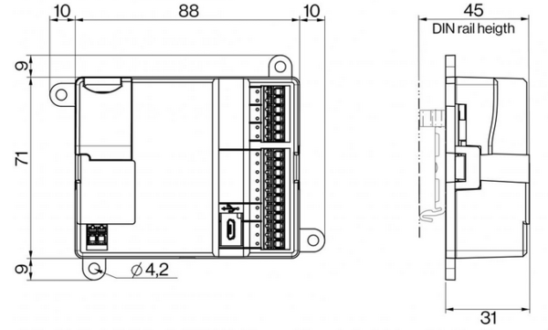
| − | + | =Dimensions CPU module= | |
| − | + | [[File:TKIV Dim CPU.PNG|thumb|left|600px|TKIV+ CPU module dimensions]] | |
| − | = | ||
| − | [[File:TKIV CPU | ||
<br clear=all/> | <br clear=all/> | ||
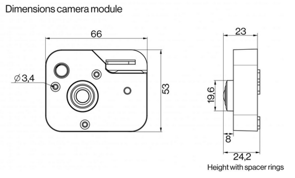
| − | + | =Dimensions Camera module= | |
| − | = | + | [[File:TKIV Dim Cam.PNG|border|left|600px|TKIV+ Camera Module dimensions]] |
| − | [[File:TKIV | ||
<br clear=all/> | <br clear=all/> | ||
| − | |||
=TKIV+ Camera Module Mounting instruction= | =TKIV+ Camera Module Mounting instruction= | ||
| Line 33: | Line 20: | ||
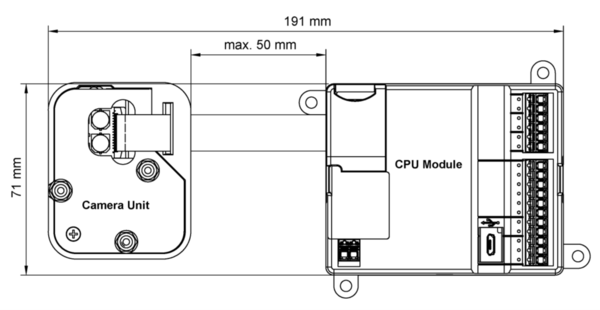
{{note|Make sure that the distance between the CPU module and the camera unit does not exceed 50 mm so as not to strain the cable.}} | {{note|Make sure that the distance between the CPU module and the camera unit does not exceed 50 mm so as not to strain the cable.}} | ||
| − | [[File:Flat_Cable_length.png|thumb|left| | + | [[File:Flat_Cable_length.png|thumb|left|600px|Flat Cable length]] |
<br clear=all/> | <br clear=all/> | ||
Latest revision as of 10:41, 10 August 2022
Contents
Dimensions CPU module
Dimensions Camera module
TKIV+ Camera Module Mounting instruction
The installation should be performed in an ESD Safe working environment using a flat-head screwdriver.
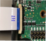
The flat cable comprises one side that has a blue tape and one side that has the contact.

|
Make sure that the distance between the CPU module and the camera unit does not exceed 50 mm so as not to strain the cable. |
Connecting the Flat Cable to the CPU Module
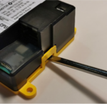
1. Use a flat-head screwdriver to release the snap locks on both short sides of the CPU module and gently pry the cover off.
|
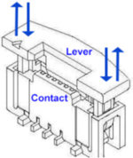
2. Open the FFC contact on the CPU board by carefully lifting the lever at both ends.
|
3. Insert the cable into the contact with the blue tape side facing up and the contact side facing down.
|
4. Close the contact by pressing down the lever at both ends simultaneously.
|
Connecting the Flat Cable to the Camera unit
- Open the FFC contact on the camera unit by carefully lifting the lever at both ends.
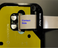
- Thread the flat cable through the strain relief on the camera unit.
- Insert the cable into the contact with the contact side facing up and the blue tape side facing down.
- Close the contact by pressing down the lever at both ends simultaneously.


