Difference between revisions of "Turbine Compact Board Connectors"
From Zenitel Wiki
(→Front) |
(→Main PCB) |
||
| Line 21: | Line 21: | ||
:Pin 5: NC relay (Normally Closed) | :Pin 5: NC relay (Normally Closed) | ||
| − | * Switching capacity: The relay can switch and carry continuously 60W power maximum. | + | * Switching capacity: The relay can switch and carry continuously 60W power maximum. E.g. with maximum current 2A, it can take maximum 30V, or with maximum voltage 250VAC it can take maximum 240mA. |
* Connectable conductors: 0.20 - 1.5 mm² (IEC) / 24 - 16 AWG (UL) | * Connectable conductors: 0.20 - 1.5 mm² (IEC) / 24 - 16 AWG (UL) | ||
Revision as of 12:20, 28 November 2017
Contents
Main PCB
Front
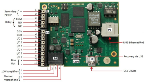
P1 RJ45 PoE port for 10/100 Mbit Ethernet connection.
- The station can be powered from this port if the line supports Power over Ethernet (PoE).
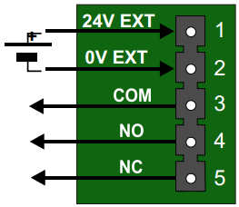
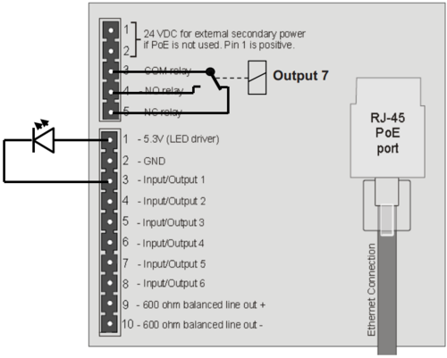
P2 5-pin plug-on terminal for relay and external power
- Pin 1/2: 24 VDC for external secondary power if PoE is not used. Pin 1 is positive.
- Pin 3: COM relay (Common)
- Pin 4: NO relay (Normally Open)
- Pin 5: NC relay (Normally Closed)
- Switching capacity: The relay can switch and carry continuously 60W power maximum. E.g. with maximum current 2A, it can take maximum 30V, or with maximum voltage 250VAC it can take maximum 240mA.
- Connectable conductors: 0.20 - 1.5 mm² (IEC) / 24 - 16 AWG (UL)
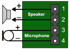
P4 Loudspeaker & Electret microphone
- Pin 1: Speaker output +
- Pin 2: Speaker output -
- Pin 3: Electret Microphone +
- Pin 4: Electret Microphone -
- Connectable conductors: 0.20 - 1.5 mm² (IEC) / 24 - 16 AWG (UL)
- Recommended loudspeaker impedance: 8 ohms
Note: To enable the electret microphone input when using a TKIS-2, the "Frontboard"
must be set to "Kit" under Station Main Settings in the web interface of the device.
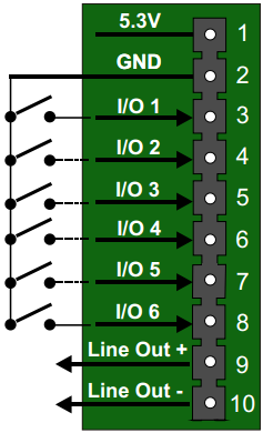
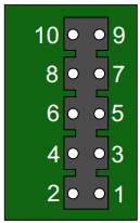
P3 10-pin plug-on terminal for I/O's and Audio Line Out
- Pin 1 5.3V (max. 200mA current)
- Pin 2 GND
- Pin 3 Button Input or LED Driver
- Pin 4 Button Input or LED Driver
- Pin 5 Button Input or LED Driver
- Pin 6 Button Input or LED Driver
- Pin 7 Button Input or LED Driver
- Pin 8 Button Input or LED Driver
- Pin 9 600 ohm balanced line out +
- Pin 10 600 ohm balanced line out -
- Connectable conductors: 0.20 - 1.5 mm² (IEC) / 24 - 16 AWG (UL)
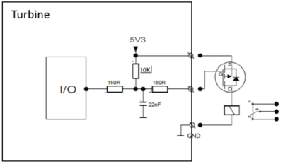
Output Connectors + 1 relay
The extra relay for any of the 6 I/O pins is connected as shown:
Most general purpose P-Channel MOSFET's should work. Recommended example: BSS84
The 5,3V output can deliver 200mA current maximum
See also Turbine Compact and MRBD
Rear
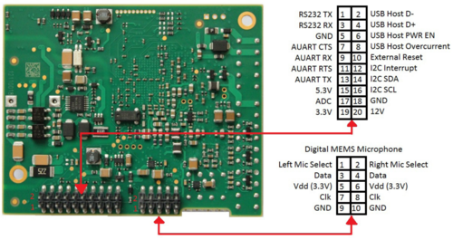
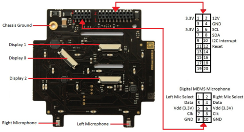
J6 10-pin terminal for digital MEMS Microphone
- Pin 1 Left mic select (Vdd)
- Pin 2 Right mic select (GND)
- Pin 3 Data
- Pin 4 Data
- Pin 5 Vdd 3.3V
- Pin 6 Vdd 3.3V
- Pin 7 CLK
- Pin 8 CLK
- Pin 9 GND
- Pin 10 GND
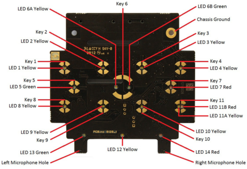
Front Board
Note! Not applicable to TKIS-2 and TMIS-x
Front
Rear


