Device I/O (Zenitel Connect Pro)
From Zenitel Wiki
Introduction
Most Zenitel devices have logical inputs and outputs. You can choose if an I/O should be used as an Input or as an Output. By default all I/O's are set as Inputs. Inputs can be used e.g. for additional external call buttons; outputs can be used to control external equipment, such as door locks or lamps for call indication.
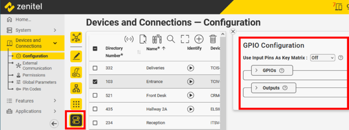
Device I/O configuration is done in Devices and Connections > Configuration. Select the device(s), then click on the icon .
The web interface will show only I/O's that are available for the selected device. Two main selections are available:
- GPIOs: Configuration of the logical Inputs/Outputs
- Outputs: Configuration of the relay(s) available in this device
 |
| Device IO settings (GPIO = General Purpose Input Output) |
It is possible to multi-select devices for I/O configuration, only those inputs and outputs which are common to all selected devices will be available for inspection and editing. Inputs and outputs which are not configured the same are indicated by
Digital Input
- Expand GPIOs and select the I/O you want to configure
- Make sure "Input/Output" is set to Input
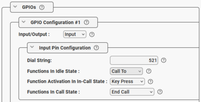
- In Dial String enter the number to dial when the input is activated
- In Functions In Call State you can choose what action to do when the input is triggered during a call:
- Answer/End Call - answer the call when the device is receiving a call, or cancel an ongoing call
- Do nothing
- End Call - cancel an ongoing call
- Answer Call - answer the call when the device is receiving a call
When enabling a "Functions In Call State" you get an option to trigger this function either when activating the input ("Key Press") or when deactivating the input ("Key Release").
 |
| Activating input #1 will generate a call to number 521. Activating the input during the call will terminate the call. |
Digital Output
- Expand GPIOs and select the I/O you want to configure
- Set "Input/Output" to Output
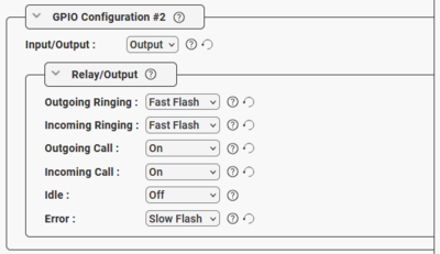
- Under "Relay/Output" select which event(s) to trigger the output. Available actions are:
- Do Nothing
- On
- Off
- Slow Flash (1.2 seconds On/Off)
- Fast Flash (0.3 seconds On/Off)
 |
| Output #2 configured for Call LED. Flashing during ringing, and steady when the call is established |
Relay
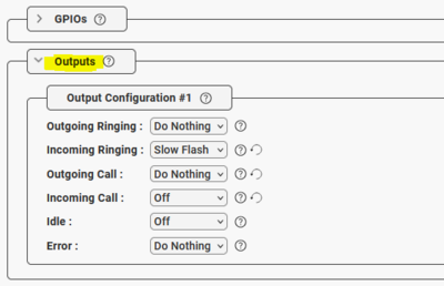
- Expand Outputs and select the Relay ("Output Configuration #1" = Relay 1) you want to configure. The number of relays available depends on the device selected.
- Select which event(s) to trigger the relay. Available actions are:
- Do Nothing
- On
- Off
- Slow Flash (1.2 seconds On/Off)
- Fast Flash (0.3 seconds On/Off)
 |
| Relay configured for Incoming Call Indication. The relay is on during incoming ringing. |

