ENA2x00-AC2 Amplifiers - Mounting and Installation
From Zenitel Wiki

This article describes the mounting and installation of the ENA2100-AC2 and ENA2200-AC2 amplifiers.
Overview - Front

| 1 | Mounting Flangex4 | The mounting flanges are used to mount the unit in 19” equipment racks |
| 2 | Ventilation Inlets | The ventilation inlets should be kept free of obstacles and dust. Fans control the airflow based on internal temperature |
| 4 | Status Indicators | The status indicators are used to display the status of important parameters such as power supplies and faults |
Overview - Back

| 1 | Ethernet Ports | Redundant Ethernet connections for audio and control data |
| 2 | Factory Reset Button | To reset the amplifier to factory default settings: Insert a straightened paper clip or similar device into the hole to press the reset button and hold for 7 to 8 seconds while powering up the amplifier. |
| 3 | Volume Bypass | Pot. meter to adjust the volume when the amplifier is in bypass mode |
| 4 | Audio Inputs | 1 line-in audio input for external audio sources |
| 5 | Control Inputs | 2 configurable control inputs. Each input is activated by closing the loop between the two terminals. |
| 6 | Control Outputs | 3 configurable control outputs. Each is made of a 24VDC signal that can source max 200mA and has overcurrent protection. |
| 7 | Fault Relay Output | A switching relay (NO, NC & COM) kept in the active position between COM and NO as long as no faults are present in the device |
| 8 | Backup Enable | Enables backup |
| 9 | Backup Inputs | 100 and 70 volt input per channel. The terminals are uninsulated. |
| 10 | Audio Outputs | 100 and 70 volt output per channel. One Channel mode is supported. The terminals are uninsulated. |
| 11 | Ground Connection | Ground connection for grounding of the unit. This is connected in parallel with the ground connection in the AC power inlet. |
| 12 | AC Power Switch | Power switch for AC power. |
| 13 | AC Power Inlet | AC power inlet for 100 to 240 VAC. The power inlet has a V-Lock mechanism for a secure connection. |
Mounting
Placement and Stacking
The amplifiers are designed to deliver full power at ambient temperatures up to 55 °C. As long as the equipment rack is well ventilated, amplifiers can be stacked with no extra space between them. It is however recommended to add 1 HU between every group of 4 amplifiers.
Mounting
The amplifier’s mechanical construction is rigid enough to be mounted using only the four holes in the mounting flange to secure it to the rack. It is however considered good practice to mount support rails if the system is installed in a mobile environment.
Use M6 x 20mm Rack Screws when fastening the amplifier to the rack.

The holes in the mounting flanges are not treaded. In a rack without treaded holes, M6 x 20mm Rack Screws with M6 Cage Nuts must be used.
Installation
Network
The Amplifier is connected to the network using one of the two Ethernet ports.

Loudspeaker Connections
The ENA2100-AC2 and ENA2200-AC2 has two different options for loudspeaker connections: 70 volts and 100 volts.
-
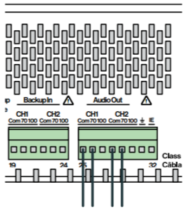 70V connection on Channel 1 and 2
 -
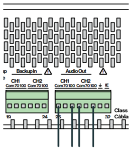 100V connection on Channel 1 and 2


Grounding
Connect a ground wire between the Ground Connection and the rack chassis. Use a ground wire of at least 0.75 mm² (AWG 19).


|
Failure to ground the amplifier to the chassis may result in electric shock to the user |

|
If the Amplifier isn’t connected to ground, it will not be able to detect ground faults or short-circuits to ground. |
Power Supply
When all wires are connected according to the system diagram, connect the equipment rack’s primary source of power to the AC Power Inlet. The cable used for power must be dimensioned accordingly to the voltage and current consumption of the amplifier. Turn on the AC Power Switch.
|
|
It is recommended not to turn on the AC Power Switch until installation is complete, as the Backup In and Audio Out have uninsulated terminals |

|
|
The power input(s) are equipped with a lock, preventing the plug from falling out. Make sure that the plug is properly inserted, and that the lock is engaged |
Fault Relay
The Amplifier’s fault relay will trigger whenever a fault occurs in the amplifier. This relay is actively kept closed by the Amplifier so it will trigger even if the entire amplifier loses power. The connection to external equipment should be made according to the external equipment’s requirements. When no faults are present in the amplifier, an electrical connection is established between the COM and NO terminals of the fault relay. When a fault is detected, or the amplifier loses power, this connection is removed and a connection between COM and NC is established.
Control Inputs
There are 2 inputs available. The inputs can be used in a conventional way, or they can be monitored. The inputs reports to the ICX-AlphaCom as input 1 and input 2.

- Conventional inputs have two states:
- Contact is Open
- Contact is Closed
Monitoring is done by connecting two resistors as close as possible to the external switch/relay, one in series and one in parallel.

The resistor connected in series with the external switch/relay shall have a value of 1 kΩ, while the resistor connected in parallel shall be 2.2 kΩ.
Monitored Inputs have four states:
- Contact is Open
- Contact is Closed
- Short circuit (error)
- Open circuit (error)
Monitoring of inputs is enabled in the web interface: Amplifier Settings > IO Monitoring > RCIs section.
Control Outputs
There are three 24V DC outputs. When used in ICX-AlphaCom mode, these outputs are mapped as pin 1, 2 and 3.
24 VDC Outputs:
- 24 VDC, ±10%, 200 mA
Audio Input
The audio input on the Amplifier can be used for background music or external alarms or any other line audio feed. The audio input should be routed to terminal blocks in the equipment rack or local audio sources.
The loudspeaker outputs from the amplifier should be routed to terminal blocks in the equipment rack according to system requirements.
|
|
Connected loudspeaker load should be less than the rated output power of the unit. Good practice is to maintain a minimum of 10%, or preferably 20% in reserve to accommodate future additional loudspeakers and avoid too much strain on the amplifier itself. |