IP Hotline Connections (INCA)
From Zenitel Wiki
INCA Based
Introduction
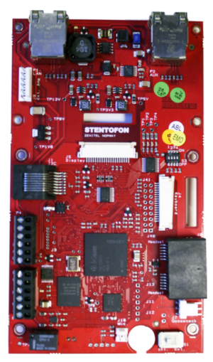
The table below is an overview of the main connectors involved when installing the IP Hotline Station.
| LAN (P1) | 10/100 Mbps RJ45 port for LAN (uplink) connection. Supports PoE (802.3af). Draws power from either spare line or signal line. |
| AUX (P2) | 10/100 Mbps RJ45 port for auxilliary equipment such as PC or IP Camera. |
| Input/Output | Pluggable screw terminal |
| Local Power | Pluggable screw terminal, 17-27 VDC Idle 4W, max. 8W |
To access these connectors the front cover must be removed.

Power Supply
The IP Hotline Station supports Power over Ethernet (PoE, IEEE 802.3 a-f) where power can be drawn from either the spare line or signal line.
If PoE is not available, the IP Hotline Station can be connected to a 24 VDC local power supply.
See Related Article INCA Master Station Kit Board Connectors for local power supply connections.
Network Connection
There are two RJ45 ports on this IP Hotline Station:
- LAN port (P1): for connecting to the network and the AlphaCom XE Audio Server.
- AUX port (P2): for connecting to auxiliary equipment such as a PC or IP Camera.
Input/Output Connections
There are I/O connection options for the IP Hotline Station. These I/O connections include:
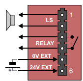
P3 - External Loudspeaker, Relay Output and External Power Input
6-pin plug-on screw terminal for external connections.

- Pin 1/2 Connection to the loudspeaker of the handset
- Pin 3/4 Internal NO relay contact for additional call indication etc.
- Pin 5/6 Connect 24 VDC for station power if PoE is not used. Pin 6 is positive.
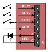
P4 - Inputs and Station LED
6-pin plug-on screw terminal for external connections.

- Pin 1/4 Input for Hookswitch for handset cradle (and for restoring Factory Default Setting)
- Pin 2/4 Input 2 (optional)
- Pin 3/4 Input 3 (optional)
- Pin 5/6 Station LED for call message info. (Pin 6 is positive.)
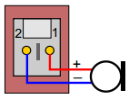
J10 - Microphone
Connection to handset microphone

- Pin 1 MIC+
- Pin 2 MIC-
Note that the microphone selection switch next to connector J10 should be in the left position, labeled "Int.".
For more details see INCA Substation Board Connectors.
