LAN Disconnect Module
From Zenitel Wiki
This article describes the installation and use of a LAN Disconnect Module to physically disconnect the network connection of a Zenitel device should a tampering event occur.
Contents
Description
- Part Number 2890010006
- Connects between the Network Switch and the Intercom unit to provide an interrupt to the connection on receipt of a tamper signal
- Allows POE to pass through
- Connects to a supplied Tamper Switch with 5k1 monitoring resistor
- Includes additional relays for protection of door open signal or external signaling
- Din rail mounted
- Reset button
- Optional tamper switch mount for Turbine intercoms in TA-1 backboxes PN 9022206001
Connections and Indications
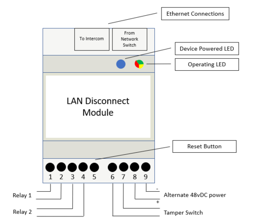
- LAN Connection to Network Switch
- LAN Connection to Intercom
- Reset button
- Connection to Tamper Switch
- Connection to external Power Supply
- 2 Relays, Closed when in normal operation
- Operating LED (Green=Normal, Yellow=Reset/Testing, Red=Tamper)
- Power Delivery LED (Blue=Power being delivered)
Installation and Operation
- Mount device to Din Rail
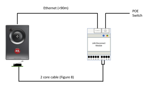
- Connect Network Switch to Ethernet input
- Connect Intercom to Ethernet Output
- Connect Tamper Switch to Tamper Switch input (Figure 8 cable required)
- Install Intercom
- Press Reset button to activate the Ethernet Output
- Observe Blue LED indicating Power supplied to endpoint, and Green LED indicating the device is operational.
- Should the Tamper Switch be disturbed, the Operational LED will turn Red, and the Blue LED will turn off.
- Press the Reset button and the device will test the Tamper Switch, indicated with a Yellow LED. If ok, the device will reset.
- If power is lost, the device will test the Tamper on power on, and activate if ok.
Tamper Switch Mount
- Part Number 9022206001
- Suitable for Turbine TCIS and TCIV+ when mounted in TA-1 backbox.
- Remove the 2 screws securing the rear housing of the turbine.
- Fit the Tamper Switch mount using the suppled screws
- Mount the Tamper Switch to the Tamper Switch mount using the supplied screws
- Tamper Switch will touch the back of the TA-1 only when correctly torqued down.
- If there is still no connection, some adjustment of the swing arm may be necessary.


