Modbus TCP
From Zenitel Wiki

Introduction
Modbus TCP is a Modbus variant used for communications over TCP/IP networks, connecting over TCP port 502. It does not require a checksum calculation as lower layers already provide checksum protection.
For background information on Modbus and its different variants please see the Modbus article in Wikipedia. Modbus is often used for data communication with PLC's.
ICX-AlphaCom and the Modbus TCP protocol
AlphaCom can send out status information in the Modbus TCP protocol via an EDO-port.
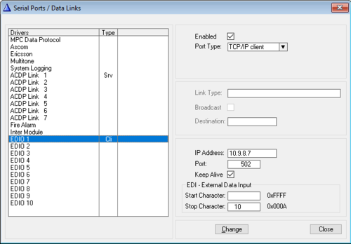
- In AlphaPro, Exchange & System > Serial Ports, select an available EDIO port, for instance EDIO 1
- Set Port Type = TCP/IP client
- Enter the IP address of the PLC to connect to
- Enter the Port number which is used by the Modbus TCP protocol, by default 502.

Modbus TCP protocol - AlphaPro programming
The exact meaning of databytes will depend on the specific installation and PLC used. This article gives an example of an implementation for a real installation, please modify as appropriate for the actual requirement. In this example the AlphaCom sends status information about each intercom station to a PLC, which uses this information for visualisation. The status is coded in a single byte, where each bit has a specific meaning.
- Bit #0: Intercom station is OK and ready for use
- Bit #1: Faulty line or faulty station
- Bit #2: Intercom station in conversation
In this example the information is written to specific registers in the PLC, 1 register for each intercom station. The PLC registers to use are from 50001 and up, related to the physical number 1 and up for the intercom stations.
The register calculation comes back in every example. The calculation is done as follows.
- Byte 0 is calculated with tmp 0 %dfmt(%op(%op(%1.phy,+,50000),/,256),c)
- %op(%1.phy,+,50000), adds 50000 to the physical address of the station
- %op(VALUE,/,256) is to shift the bits right by 8 positions
- %dfmt(VALUE,c) is used to convert it into a ASCII character
- tmp 0 is used to store the value till it will be used
- Byte 1 is calculated with tmp 1 %dfmt(%op(%1.phy,+,50000),c)
- %op(%1.phy,+,50000), adds 50000 to the physical address of the station
- %dfmt(VALUE,c) is used to convert it into a ASCII character, only the first 8 bits will be used.
- tmp 1 is used to store the value till it will be used
Example: Station OK and ready for use
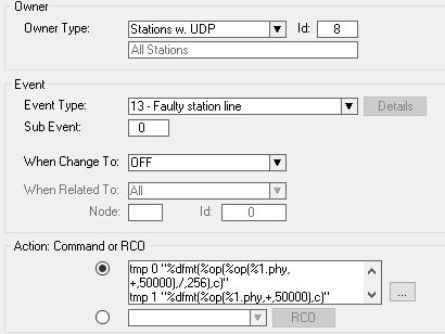
Program an event:

- Owner Type: Station with UDP 8
- Event Type: 13 - Faulty station line
- When Change To: OFF
Action commands:
tmp 0 "%dfmt(%op(%op(%1.phy,+,50000),/,256),c)"
tmp 1 "%dfmt(%op(%1.phy,+,50000),c)"
EDO 1 "\0\x01\0\0\0\x06\x02\x06%tmp(0)%tmp(1)\0\x01"
In this specific case the meaning of the bytes is:
- \0\x01 - Transaction Identifier; 2 bytes
- \0\0 - Protocol Identifier; 2 bytes; always '0' for Modbus TCP
- \0\x06 - Length Field; 2 bytes; Number of remaining bytes in this frame
- \x02 - Unit Identifier; 1 byte; Slave Address (255 if not used)
- \x06 - Function code; 1 byte; Function codes as in other variants - 6: Write single register
- %tmp(0)%tmp(1)\0\x01 - Data bytes; the data used for the function code - For this specific function code this is 4 bytes, 2 bytes to address the register and 2 bytes for the data to be written.
- The first two bytes are the register address, %tmp(0)%tmp(1), as calculated in the introduction
- The next two bytes are the value being written to this register: \0\x01, Value 1 sets bit #0 and resets all the rest. The leading \0 does byte stuffing for the high order byte.
Example: Station line error
Program an event:
- Owner Type: Station with UDP 8
- Event Type: 13 - Faulty station line
- When Change To: ON
Action commands:
tmp 0 "%dfmt(%op(%op(%1.phy,+,50000),/,256),c)"
tmp 1 "%dfmt(%op(%1.phy,+,50000),c)"
EDO 1 "\0\x01\0\0\0\x06\x02\x06%tmp(0)%tmp(1)\0\x02"
In this specific case the meaning of the bytes is:
- \0\x01 - Transaction Identifier; 2 bytes
- \0\0 - Protocol Identifier; 2 bytes; always '0' for Modbus TCP
- \0\x06 - Length Field; 2 bytes; Number of remaining bytes in this frame
- \x02 - Unit Identifier; 1 byte; Slave Address (255 if not used)
- \x06 - Function code; 1 byte; Function codes as in other variants - 6: Write single register
- %tmp(0)%tmp(1)\0\x02 - Data bytes; the data used for the function code - For this specific function code this is 4 bytes, 2 bytes to address the register and 2 bytes for the data to be written.
- The first two bytes are the register address, %tmp(0)%tmp(1), as calculated in the introduction
- The next two bytes are the value being written to this register: \0\x02, Value 2 sets bit #1 and resets all the rest. The leading \0 does byte stuffing for the high order byte.
Example: Station in conversation
Program an event:
- Owner Type: Station with UDP 8
- Event Type: 44 - Conversation
- When Change To: ON
Action commands:
tmp 0 "%dfmt(%op(%op(%1.phy,+,50000),/,256),c)"
tmp 1 "%dfmt(%op(%1.phy,+,50000),c)"
EDO 1 "\0\x01\0\0\0\x06\x02\x06%tmp(0)%tmp(1)\0\x04"
PAUSE
PAUSE
In this specific case the meaning of the bytes is:
- \0\x01 - Transaction Identifier; 2 bytes
- \0\0 - Protocol Identifier; 2 bytes; always '0' for Modbus TCP
- \0\x06 - Length Field; 2 bytes; Number of remaining bytes in this frame
- \x02 - Unit Identifier; 1 byte; Slave Address (255 if not used)
- \x06 - Function code; 1 byte; Function codes as in other variants - 6: Write single register
- %tmp(0)%tmp(1)\0\x04 - Data bytes; the data used for the function code - For this specific function code this is 4 bytes, 2 bytes to address the register and 2 bytes for the data to be written.
- The first two bytes are the register address, %tmp(0)%tmp(1), as calculated in the introduction
- The next two bytes are the value being written to this register: \0\x04, Value 4 sets bit #2 and resets all the rest. The leading \0 does byte stuffing for the high order byte.
Example: Station ends conversation
Program an event:
- Owner Type: Station with UDP 8
- Event Type: 44 - Conversation
- When Change To: OFF
Action commands:
tmp 0 "%dfmt(%op(%op(%1.phy,+,50000),/,256),c)"
tmp 1 "%dfmt(%op(%1.phy,+,50000),c)"
EDO 1 "\0\x01\0\0\0\x06\x02\x06%tmp(0)%tmp(1)\0\x01"
PAUSE
PAUSE
In this specific case the meaning of the bytes is:
- \0\x01 - Transaction Identifier; 2 bytes
- \0\0 - Protocol Identifier; 2 bytes; always '0' for Modbus TCP
- \0\x06 - Length Field; 2 bytes; Number of remaining bytes in this frame
- \x02 - Unit Identifier; 1 byte; Slave Address (255 if not used)
- \x06 - Function code; 1 byte; Function codes as in other variants - 6: Write single register
- %tmp(0)%tmp(1)\0\x01 - Data bytes; the data used for the function code - For this specific function code this is 4 bytes, 2 bytes to address the register and 2 bytes for the data to be written.
- The first two bytes are the register address, %tmp(0)%tmp(1), as calculated in the introduction
- The next two bytes are the value being written to this register: \0\x01, Value 1 sets bit #0 and resets all the rest. The leading \0 does byte stuffing for the high order byte.
Notes: \x is the escape code to indicate that the following value is hexadecimal; 0 should be send as \0
Verifying the configuration and operation
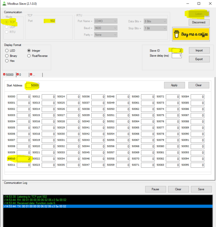
A Modbus TCP Slave test tool can be used to verify the configuration and operation.
Download and install a test tool (e.g. ClassicDIY/ModbusTool). Pay attention to the highlighted settings in the image below.
In this example the station with physical number 10 is reported faulty. The register 50000 + 10 = 50010 is then set to the value 2 (= Faulty Station).


