|
| The Zenitel VAIA unit |
The Zenitel VAIA is a combined PAVA audio router and amplifier in one. The 1U unit houses 4 duty amplifiers and an additional back up amplifier. The VAIA as a whole has a maximum audio power of 1000 Watt with a maximum of 500 Watt for any individual amplifier.
An inbuild battery charger makes the VAIA a full EN54-4 and EN54-16 capable unit.
The frontpanel
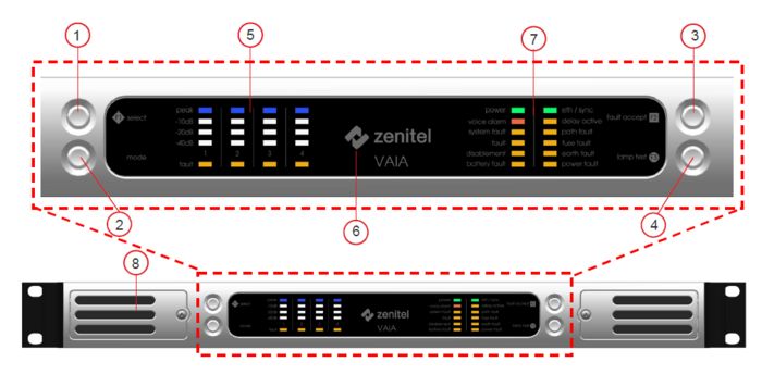 |
| The frontpanel overview |
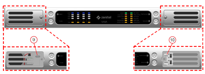 |
| The frontpanel protected controls |
- Select button F1 - has no current function when pressing. If the button is lit blue it means a firmware upgrade is in progress
- Mode - Long press (> 5 seconds) puts the VAIA in identify mode. A short press cancels identify mode.
- Fault accept F2 - When flashing there are unaccepted fault. Steady lit means all current faults are accepted. A short press can be used to accept faults
- Lamp test F3 - Pressing this button will turn on all LED indications and sounders to test their functionality
- Amplifier indications - There are 4 LEDs indicating the power and one to indicate fautls
- Zenitel logo - Flashing indicates booting and steady lit is normal operation
- General indicators:
- Power (green) - Steady lit when the unit is powered
- Voice alarm (red) - Lit to indicate a Voice alarm condition is present in the system
- System fault (orange) - Lit to indicate a system fault e.g. processor or memory
- Fault (orange) - Indicates a fault. Flashing means unaccepted faults, steady means accepted
- Disablement (orange) - Reserved for future use
- Battery fault (orange) - Indicates a fault with the battery
- Eth/sync (green) - Lit to indicate an ethernet connection is present. Flashing means the unit is syncing with the NTP clock
- Delay active (orange) - Reserved for future use
- Path fault (orange) - Lit to indicate a fault in the audio path. This could affect VA announcements
- Fuse fault (orange) - Indicates a fault in a part of the power system, including the battery
- Earth fault (orange) - Lit to indicate a earthing problem
- Power fault (orange) - Indicates a fault in the mains or battery power.
- Loudspeaker - Fault sounder
- USB-C serial port - For debugging
- Mains and Battery switch - Used to turn of the mains or battery power supply
The connections
The power connections
There are 4 connections on the VAIA regarding the power. In the below picture they are from left to right:
- The AC connection, this is a C19 plug for connection the incoming 110-230 VAC
- A two pin Phoenix connector for the NTC probe for the battery pack
- A two pin Phoenix connector for powering additional equipement in the rack
- A two pin connector for connecting the 24V battery pack (two 12V batteries in series)
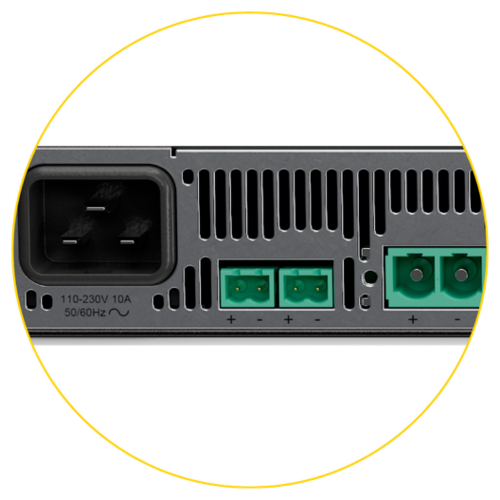 |
| The power connections |
The speakerline connections
There are 4 groups of connectorblocks for the speaker lines. One group for each internal amplifier. The outputs of the amplifier are divided into four identical lines: A, B, C, and D.
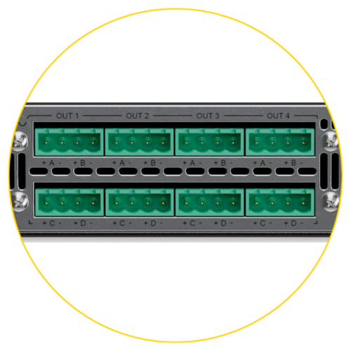 |
| The speakerline connections |
The audio input connections
The VAIA has 6 audio inputs, two for Zenitel analogue microphones like the MPS and EMS, and 4 for generic balanced line level input sources.
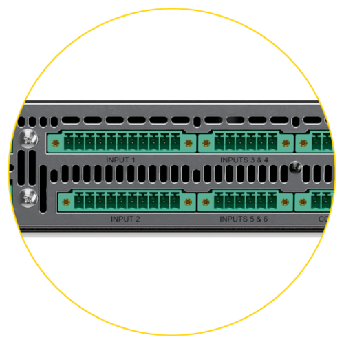 |
| The audio input connections |
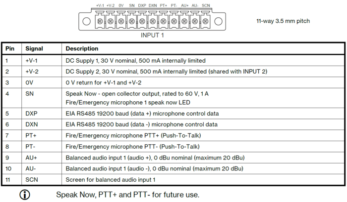 |
| The audio input 1 pinout |
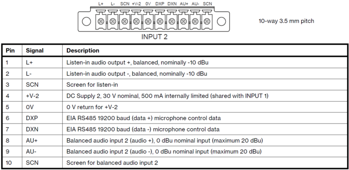 |
| The audio input 2 pinout |
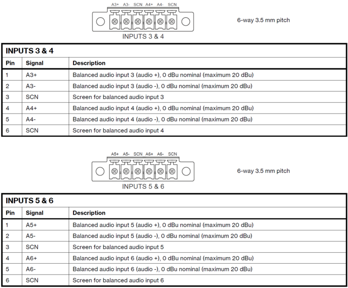 |
| The audio input 3 to 6 pinout |
The GPI, auxiliary, and network connections
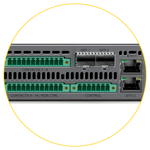
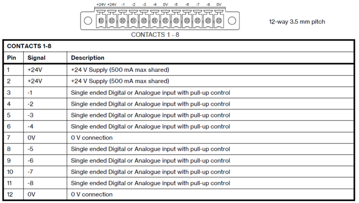
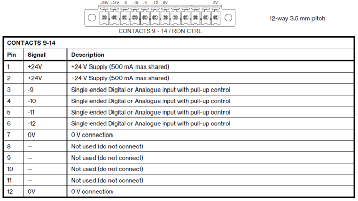
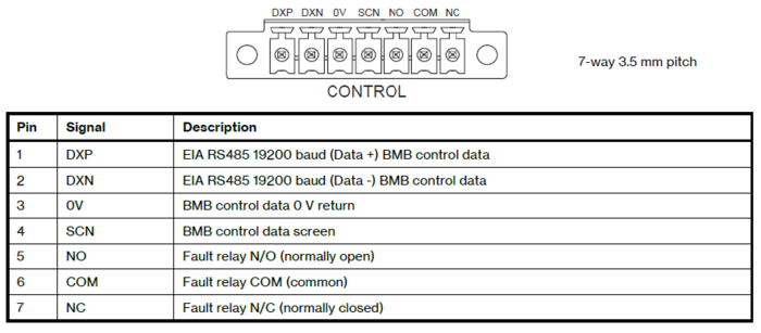
In the last group of connectors are the general purpose inputs, fault relay, and RS485 connection for the BMB02 remote IO units. At the far end there is also the network connections.
 |
| The auxiliary connections |
 |
| The contacts 1-8 pinout |
 |
| The contacts 9-14 pinout |
 |
| The control pinout |
At the far right of the backside of the VAIA there are 4 network connections. Two of the connections are standard RJ45 and the other two are slots for SFPs so that the VAIA can be connected via a optical fibre connection.
Configuring the VAIA
The configuration of the VAIA is described in the seperate article Zenitel VAIA Configuration