Difference between revisions of "IP Video Door Station - 1401110100"
From Zenitel Wiki
(→Board Connectors) |
(→Reset to factory settings) |
||
| Line 43: | Line 43: | ||
==Reset to factory settings== | ==Reset to factory settings== | ||
| − | |||
| − | |||
==Related articles== | ==Related articles== | ||
Revision as of 12:25, 25 October 2016
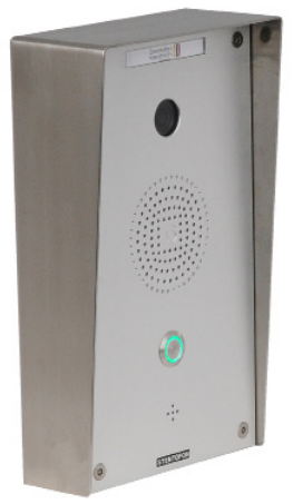
Camera Type: CP-Cam
- Default IP adresses:
- Audio module: 169.254.1.100 (admin/alphaadmin)
- Camera module: 169.254.1.101 (admin/1234)
Contents
- 1 Highlights
- 2 InterCom connections
- 3 IP Station Configuration
- 4 Software Upgrade
- 5 LED Indications
- 6 Board Connectors
- 7 Dimensions
- 8 Reset to factory settings
- 9 Additional Documentation on Zenitel.com
- 10 Installation
- 11 Station Board Connectors and LED Indications
- 12 IP Station Configuration
- 13 Reset to factory settings
- 14 Related articles
- 15 Camera Configuration
Highlights
- Robust housing with Aluminium frontplate
- IP65 protection to front
- Powered from the IP network cable using Power over Ethernet (PoE)* PoE Powered from one IP network cable
- Relay output for remote control, e.g. doors, signal lamps and gates
- Button with bi-colour LED ring
InterCom connections
IP Station Configuration
Software Upgrade
LED Indications
Board Connectors
Dimensions
Reset to factory settings
Additional Documentation on Zenitel.com
Installation
See article: IP Station Installation
Station Board Connectors and LED Indications
See article: IP Station Board Connections and Indications
IP Station Configuration
See article: IP Station Configuration
Reset to factory settings
Related articles
Camera Configuration
Connect to the camera using a webbrowser on default IP address 169.254.1.101.
In the menu that appears, click System Settings, and you will be asked to login:
Username: admin
Password: 1234
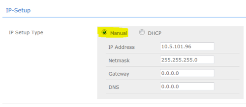
It is recommended to use a static IP address for the camera:
From the Main Menu navigate to System Settings -> Camera:
CameraWeb
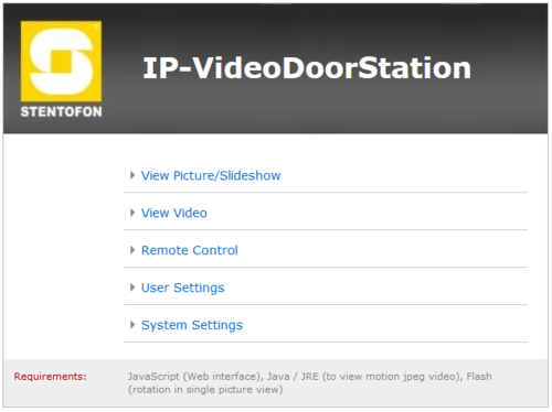
Main Menu
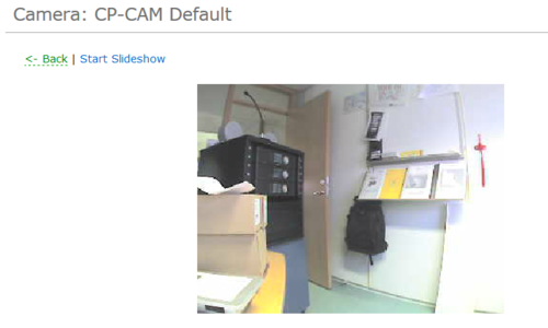
View Picture/Slideshow
This option is used to display single pictures fo the camera.
By clicking Start, the camera starts displaying a picture every second.
With Stop, the current picture is permanently displayed.
With Back, you return to the main menu.
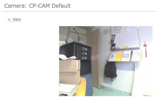
View Video
With this selection, the video images are displayed.
Settings for the displayed video can be found under Settings -> Camera.
With Back, you return to the main menu.
Remote Control
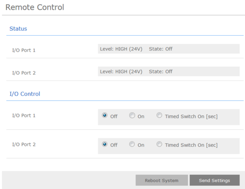
The CP-CAM can, in conjunction with an IO interface, provide two opto-coupler inputs or two relay outputs.
A door opener or light can for example be switched vie the web interface using the outputs.
Status
I/O Port 1 - Shows the status of the first I/O input
I/O Port 2 - Shows the status of the second I/O input
I/O Control
I/O Port 1 - The switching state of the first output can be set here
I/O Port 2 - The switching state of the second output can be set here
Off - Output alway off
On - Output is permanently switched on
Timed Switched On - Here, the output can be set for a given time period
Reboot System - Restarts the CP-CAM
Send Settings - Sends the settings to the camera to be effective
User Setup
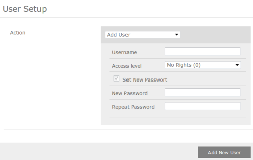
In this menu the users of the CP-CAM can be managed. A user can be assigned different permissions.
The availability of the video and picture display without password entry can be set under Settings->Network.
Action - Ability to add, change or detele a user
Username - In this field, user name is entered (no special characters allowed)
Access Level - Selection of authorixzation for a user
- No rights (0) - User is deactivated
- Viewer (2) - User has access to single picture and video display, as well as for the camera ID
- Remote Control (4) - User has additionally access to remote control
- Administration (8) - User has unrestricted access
Set New Password - Enter password
Repeat Password - Confirm password
Add New User/Change/Delete - By clicking on this button, the settings are applied
With Back, you return to the main menu
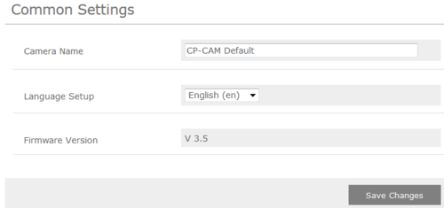
Common Settings
Camera Name - The name of the camera can be set here, which is displayed as header above the video window. The name is also displayed in the password prompt window.
Firmware version - The installed software version on the CP-CAM is shown here.
Save Changes - Saves the settings permanently and you return to the main menu.
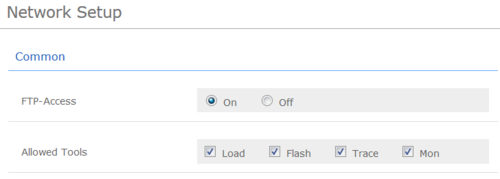
Network Setup
FTP-Access - FTP access to the data of the CP-CAM can be turned on here
Allowed Tools - Specifies which support program that are allowed to access the CP-CAM
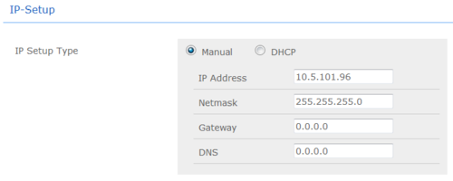
IP Setup Type
- Manual/DHCP - Specifies whether the network settings are to be manually or automatically assigned
- IP Address - IP address at which the CP-CAM can be reached on the network
- Netmask - The netmask is entered here
- Gateway - Gateway is entered here
- DNS - DNS server is specified here
Ethernet Mode - Standard settings should always be set to Auto. The other settings are only for network professional in the event of problems with the automatic
MAC Address - MAC address of the camere
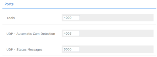
Note! The following port numbers must all have different values, as this can cause malfunction
Tools - Port for support programs
UDP-Autoomatic Cam Detection - UDP port for automatic detection of camera in the network using special software
UDP-Status Messages - UDP port for status messages
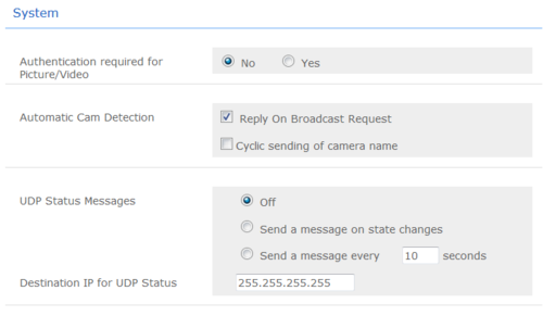
Authentication required for picture/video - Specifies whether the user requires a password for the video and picture display
Automatic Cam Detection - Must be turned on to automatically detect several cameras over the network. Must be turned off after system installation, particularly in network where many broadcasts are sent
UDP Status Messages - Settings for status messages
Off - Camera sends no status messages
Message after mode change - A message is sent after each mode change. (I/O, camera driver and LED mode)
Cyclical message - An additional message is sent after a time interval - even if there has been no mode change
Destination IP for UDP Status - Destination address of status messages
Save Changes - Saves the settings permanently and you return to the main menu
Camera Setup
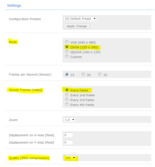
Settings
Configuration Presets - Here you can select on of several configuration sets of camera settings.
Warning! All other changes will be lost. Therefore, you should first change the default settings and then the other!
Mode - Sets the camera resolution
Number of frames per second - Defines the number of pictures per second which the video sensor captures. With VGA max 15 (20 at quality 40), by QVGA/QQVGA max 25
Shown Frames - Specifies how many of the captured pictures are transmitted as video. Only every X-th picture is sent
Zoom - Setting of the picture enlargement
- Zooming is only possible with a resolution smaller than VGA (640x480).
- The zoom factor can only be as large as the factor which reduced the picture.
- So with QQVGA max 4.0x.
- A value to large is automatically reset to 1.0x.
- Generally:
- (ResolutionX * Zoom)<640
- (ResolutionX * Zoom)<480
Displacement on X-Axis/Y-Axis - It is possible to adjust a picture (only at resolutions < VGA). To view a certain section of the picture, move the section in the X and Y direction so far until the desired picture is visible. Incorrect values are corrected automatically!
- Example: At a resolution of 320x240 and 2x zoom, the center of the picture should be displayed. Th epicture must be adjusted 160 pixels in the X direction and 120 pixels in the Y direction!
Quality (JPEG compression) - A lower quality should be chosen in case the network bandwidth is not sufficient (too many users)
IR Lighting/Nightvision
IR Lighting Setup - Selection of IR lighting mode
Always off - IR lighting permanently off
Always on - IR lighting permanently on
Automatic - The camera measures the brightness and, if necessary, turns on the light automatically
Controlled by I/O - IR lighting is controlled with the 2 I/O ports
Options-IR Automaitc Mode - Specifies that the IR lighting can be overridden with the two I/O ports despite automatic mode
Override by I/O's disabled - No response when I/O ports are switched
Override Option 1 - If the I/O port is ON, the IR lighting is switched on by force
Override Option 2 - If the I/O port is on, the IR lighting is switched on by force
Options-IR Controlled by I/O's - Determines whether the IR control via the I/O ports are to be normal or inverted
IR mode threshold (Shutter) - Determination of the switching threshold (shutter - light intesity)
Hysteresis - Hysteresis for switching threshold. Switching threshold ON = switching threshold + hysteresis. Switching threshold OFF = switching threshold - hysteresis
Switch On Delay - Waiting time after exceeding the threshold on until switching occurs
Switch Off Delay - Waiting time after falling below the threshold off until switching occurs
B/W in IR/Nightvision mode - Indicates whether the night vision should be switched to black/white mode
Video
Picture Rotation in Video Applet - The CP-CAM is capable of rotating the displayed picture in 90° increments, the installation position of the CP-CAM can therefore be selected. The rotation is only for the viewing in the web interface. The pictures and the motion JGPEG stream, which can be accessed over http://<camera-IP>/jpg and http://<camera-IP>/mjpg/video.mjpg respectively, are always in original position. Th eclient software resumes the picture rotation
Single pictures can only be rotated when the web browser supports Flash and has it installed.
System Info
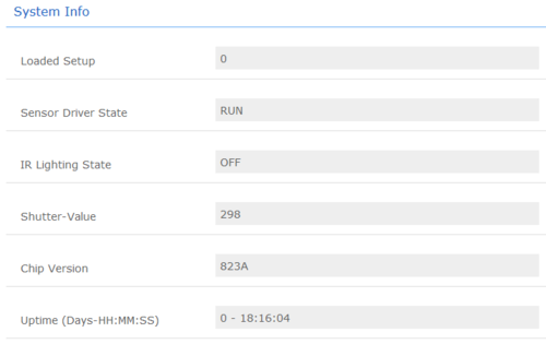
Loaded Setup - Shows which presettings were loaded
Sensor Driver State - Status mode of the camera driver. Should always be on RUN, otherwise the camera must be restarted
IR Lighting State - Shows whether the infrared lighting is turned on or off
Shutter-Value - Shows the current position of the integrated lens aperture of the camera. This panel provides automatic exposure compensation. This value allows conclusions to be drawn of the intensity of the current lighting. The larger the value, the less ambient light.
Chip Version - Version of the built-in video chips
Save Changes - Saves the settings permanently and you return to the main menu
CP-Cam IP address Reset
This should be carried out only by experienced technicians. The customer is liable for damages caused by improper opening of the housing.
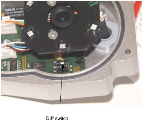
If the entered IP address is unknown, it is possible to reset the address to 10.10.10.10 using the DIP switch. To proceed, the unit must be opened.
Note: A change of the IP address is made via the web interface of the CP-CAM.
The procedure is as follows:
- 1. Power off the station
- 2. Open the CP-CAM so the two DIP switches are accessible ( see picture ).
- 3. Note the switch position and then turn both switches to "OFF".
- 4. Power On the station
- 5. Connect PC with the IP number range 10.10.10.xxx and log in.
- 6. Turn switch positions back to original positions.
- 7. Set the desired IP address in the web interface. Press "Save Changes"
- 8. Reboot station
- 9. Close housing properly.

