ITSV-1: Difference between revisions
From Zenitel Wiki
No edit summary |
No edit summary |
||
| (7 intermediate revisions by 3 users not shown) | |||
| Line 1: | Line 1: | ||
{{ | {{Obsolete}} | ||
[[Image:ITSV-1.png|thumb|300px|IP Phone ITSV-1 ( | {{AEIPS}} | ||
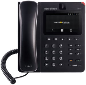
[[Image:ITSV-1.png|thumb|300px|IP Phone ITSV-1 (1490001010)]] | |||
This product is replaced by [[ITSV-2]] | |||
== Getting Started == | == Getting Started == | ||
| Line 32: | Line 35: | ||
* [[ITSV-1 (Pulse)|ITSV-1 Configuration - Pulse mode]] | * [[ITSV-1 (Pulse)|ITSV-1 Configuration - Pulse mode]] | ||
* [[ITSV-1 (Edge)|ITSV-1 Configuration - Edge mode]] | * [[ITSV-1 (Edge)|ITSV-1 Configuration - Edge mode]] | ||
== Restore Factory Defaults and Software Upgrade == | |||
* [[ITSV-1 Restore Factory Defaults|Restore Factory Defaults]] | |||
* [[ITSV-1 - Software Upgrade|Upgrade via the ITSV-1 web interface]] | |||
== Dimensions == | == Dimensions == | ||
| Line 48: | Line 57: | ||
* [https://www.zenitel.com/product/itsv-1 Documentation on Zenitel.com] | * [https://www.zenitel.com/product/itsv-1 Documentation on Zenitel.com] | ||
[[Category: | [[Category: Discontinued Stations]] | ||
Latest revision as of 09:26, 18 March 2022
This product is replaced by ITSV-2
Getting Started
Installing the Phone with Wall Mount
- Attach the wall mount to the slots on the back of the phone.
- Attach the phone to the wall via the wall mount hole.
- Pull out the tab from the handset cradle (see figure below).
- Rotate the tab and plug it back into the slot with the extension up to hold the handset while the phone is mounted on the wall.
Installing the Phone with Phone Stand
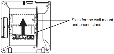
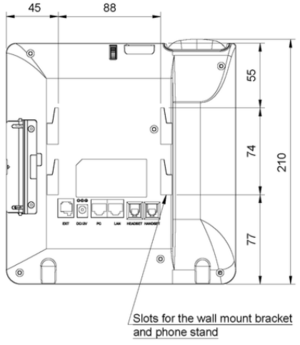
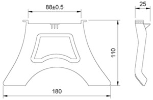
Attach the phone stand to the back of the phone where there are slots for mounting. The upper and bottom slots enable mounting at two different angles.
Connecting the phone
- Connect the handset and main phone case with the phone cord.
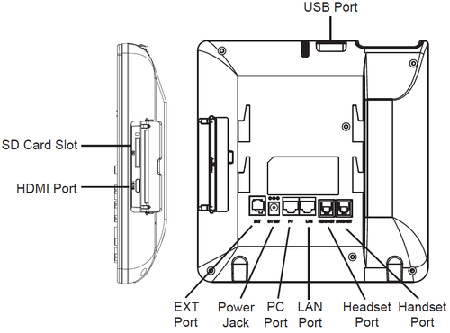
- Connect the LAN port of the phone to the RJ-45 socket of a hub/switch or a router (LAN side of the router) using the Ethernet cable.
- If you have a compatible power adapter, connect the 12V DC output plug to the power jack on the phone; plug the power adapter into an electrical outlet. (If PoE switch is used in step 2, this step could be skipped.)
- The LCD will display booting up or firmware upgrading information. Before continuing, please wait for the main screen display to appear.
- Using the web configuration interface or the menu of the touch screen, you can further configure network connection using static IP, DHCP, etc.
Configuration
The IP phone can only operate in SIP mode. Choose one of the links below depending on what kind of server the station should register to.
- ITSV-1 Configuration - AlphaCom mode
- ITSV-1 Configuration - Pulse mode
- ITSV-1 Configuration - Edge mode
Restore Factory Defaults and Software Upgrade
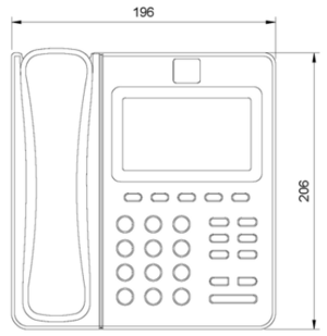
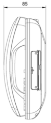
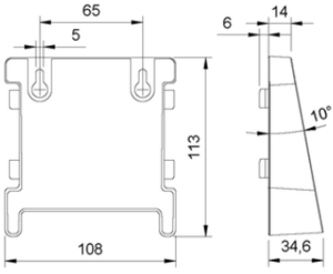
Dimensions
- Phone dimensions
- Bracket dimensions


