ECP-AA1 Connections: Difference between revisions
From Zenitel Wiki
(Created page with "{{AEIPS}} The ECP-AA1 has 2 connectors located at the bottom of the unit. == Power == The ECP-AA1 is powered through the Ethernet connector via Power over Ethernet (PoE). T...") |
No edit summary |
||
| (One intermediate revision by one other user not shown) | |||
| Line 2: | Line 2: | ||
The ECP-AA1 has 2 connectors located at the bottom of the unit. | The ECP-AA1 has 2 connectors located at the bottom of the unit. | ||
== Power == | ==Power== | ||
The ECP-AA1 is powered through the Ethernet connector via Power over Ethernet (PoE). | The ECP-AA1 is powered through the Ethernet connector via Power over Ethernet (PoE). | ||
| Line 10: | Line 10: | ||
<br style="clear:both;" /> | <br style="clear:both;" /> | ||
== Ethernet connector == | ==Ethernet connector== | ||
Type: M12, D-coded, Female, 4-pin | Type: M12, D-coded, Female, 4-pin | ||
[[File:ECP-AA1 Connector1.png|left|thumb]] | [[File:ECP-AA1 Connector1.png|left|thumb]] | ||
| Line 16: | Line 16: | ||
{| border="1" | {| border="1" | ||
|- | |- | ||
| 1 || TD+ | |1||TD+ | ||
|- | |- | ||
| 2 || RD+ | |2||RD+ | ||
|- | |- | ||
| 3 || TD- | |3||TD- | ||
|- | |- | ||
| 4 || RD- | |4||RD- | ||
|} | |} | ||
<br style="clear:both;" /> | <br style="clear:both;" /> | ||
== I/O connector == | ==I/O connector== | ||
Type: M12, A-coded, Fermale, 8-pin | Type: M12, A-coded, Fermale, 8-pin | ||
[[File:ECP-AA1 Connector2.png|left|thumb]] | [[File:ECP-AA1 Connector2.png|left|thumb]] | ||
| Line 32: | Line 32: | ||
{| border="1" | {| border="1" | ||
|- | |- | ||
| 1 || +5V DC | |1||+5V DC | ||
|- | |- | ||
| 2 || GND | |2||GND | ||
|- | |- | ||
| 3 || I/O 1 | |3||I/O 1 | ||
|- | |- | ||
| 4 || I/O 2 | |4||I/O 2 | ||
|- | |- | ||
| 5 || I/O 3 | |5||I/O 3 | ||
|- | |- | ||
| 6 || Relay - common | |6||Relay - common | ||
|- | |- | ||
| 7 || Relay - NC | |7||Relay - NC | ||
|- | |- | ||
| 8 || relay - NO | |8||relay - NO | ||
|} | |} | ||
== | ==Connection to Emergency Break== | ||
The emergency | The emergency brake provides a clean contact to the ECP-AA1. Its purpose is so that an emergency call is made as soon as the emergency brake handle is operated. | ||
<u>'''Procedure'''</u> | <u>'''Procedure'''</u> | ||
== Connection to CCTV System == | *Connect the clean contact between pins 2 and 3 on the I/O connector. | ||
==Connection to CCTV System== | |||
The ECP-AA1 provides a clean contact to the CCTV system. Its purpose is to send a trigger to the CCTV system when a call is made from the ECP-AA1. | The ECP-AA1 provides a clean contact to the CCTV system. Its purpose is to send a trigger to the CCTV system when a call is made from the ECP-AA1. | ||
<u>'''Procedure'''</u> | <u>'''Procedure'''</u> | ||
* Connect the CCTV trigger input between pins 6 and 8 on the I/O connector. | |||
*Connect the CCTV trigger input between pins 6 and 8 on the I/O connector. | |||
==Related== | |||
[[Turbine Compact series board connectors]] | |||
[[Category: Turbine Connections]] | [[Category: Turbine Connections]] | ||
Latest revision as of 11:10, 23 June 2023
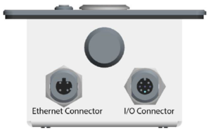
The ECP-AA1 has 2 connectors located at the bottom of the unit.
Power
The ECP-AA1 is powered through the Ethernet connector via Power over Ethernet (PoE).
The Ethernet connector is located at the bottom of the unit:
Ethernet connector
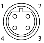
Type: M12, D-coded, Female, 4-pin
| 1 | TD+ |
| 2 | RD+ |
| 3 | TD- |
| 4 | RD- |
I/O connector
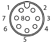
Type: M12, A-coded, Fermale, 8-pin
| 1 | +5V DC |
| 2 | GND |
| 3 | I/O 1 |
| 4 | I/O 2 |
| 5 | I/O 3 |
| 6 | Relay - common |
| 7 | Relay - NC |
| 8 | relay - NO |
Connection to Emergency Break
The emergency brake provides a clean contact to the ECP-AA1. Its purpose is so that an emergency call is made as soon as the emergency brake handle is operated.
Procedure
- Connect the clean contact between pins 2 and 3 on the I/O connector.
Connection to CCTV System
The ECP-AA1 provides a clean contact to the CCTV system. Its purpose is to send a trigger to the CCTV system when a call is made from the ECP-AA1.
Procedure
- Connect the CCTV trigger input between pins 6 and 8 on the I/O connector.


