ECP-AA1 Connections
From Zenitel Wiki

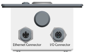
The ECP-AA1 has 2 connectors located at the bottom of the unit.
Power
The ECP-AA1 is powered through the Ethernet connector via Power over Ethernet (PoE).
The Ethernet connector is located at the bottom of the unit:

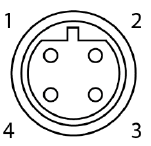
Ethernet connector
Type: M12, D-coded, Female, 4-pin

| 1 | TD+ |
| 2 | RD+ |
| 3 | TD- |
| 4 | RD- |
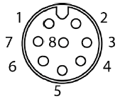
I/O connector
Type: M12, A-coded, Fermale, 8-pin

| 1 | +5V DC |
| 2 | GND |
| 3 | I/O 1 |
| 4 | I/O 2 |
| 5 | I/O 3 |
| 6 | Relay - common |
| 7 | Relay - NC |
| 8 | relay - NO |
Connection to Emergency Break
The emergency brake provides a clean contact to the ECP-AA1. Its purpose is so that an emergency call is made as soon as the emergency brake handle is operated.
Procedure
- Connect the clean contact between pins 2 and 3 on the I/O connector.
Connection to CCTV System
The ECP-AA1 provides a clean contact to the CCTV system. Its purpose is to send a trigger to the CCTV system when a call is made from the ECP-AA1.
Procedure
- Connect the CCTV trigger input between pins 6 and 8 on the I/O connector.
