Difference between revisions of "Touchless sensor (w/ backbox)"
From Zenitel Wiki
(→Highlights) |
|||
| (55 intermediate revisions by 3 users not shown) | |||
| Line 1: | Line 1: | ||
| − | [[File:2390020100 touchless sensor 1.jpg|thumb| | + | [[File:2390020100 touchless sensor 1.jpg|thumb|200px|right|Touchless sensor, item 2390020100]] |
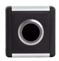
| − | The '''Touchless sensor''' (item 2390020100) is an IR-sensor that connects to | + | The '''Touchless sensor''' (item 2390020100) is an IR-sensor that connects to Zenitel IP stations, and is used to activate calls with gesture recognition instead of pressing the call button. |
| + | |||
| + | The sensor button is powered by 5 volts. Most Zenitel IP stations has a built-in 5V output which can be used to power the sensor button. | ||
== Highlights == | == Highlights == | ||
| + | <div style="float:right;"> <youtube width="350" height="210">3yYBW2ADsNI</youtube> </div> | ||
* Input Voltage: 5V | * Input Voltage: 5V | ||
* Available contacts: Normally Open & Normally Closed | * Available contacts: Normally Open & Normally Closed | ||
| − | * Operating distance | + | * Sensor active time: 0,5 secs |
| − | * | + | * Operating distance: 15cm |
| + | * IP66 | ||
== Connections == | == Connections == | ||
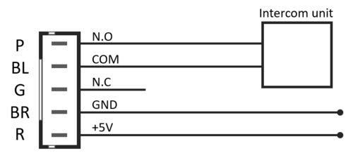
Connections are made to the switch using the supplied 5 pin plug. <br> | Connections are made to the switch using the supplied 5 pin plug. <br> | ||
Correct orientation of the plug is ensured by the connector locating guides. | Correct orientation of the plug is ensured by the connector locating guides. | ||
| + | |||
=== Color code === | === Color code === | ||
* Red - +5 Volt supply | * Red - +5 Volt supply | ||
| Line 18: | Line 23: | ||
* Blue - Common | * Blue - Common | ||
* Purple - Normally Open | * Purple - Normally Open | ||
| − | |||
| − | |||
| − | |||
| − | |||
== Typical Application == | == Typical Application == | ||
| Line 27: | Line 28: | ||
<br style="clear:both;" /> | <br style="clear:both;" /> | ||
| − | == | + | == Use Case Examples == |
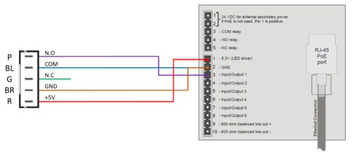
| − | [[File:Touchless sensor wiring example.png|thumb|500px|left|Touchless sensor - | + | Touchless sensor - wiring example: |
| + | |||
| + | [[File:Touchless sensor wiring example.png|thumb|500px|left|Touchless sensor wired to Input 1 on a Turbine station]] | ||
| + | <br style="clear:both;" /> | ||
| + | |||
| + | === Configuration on IC-Edge === | ||
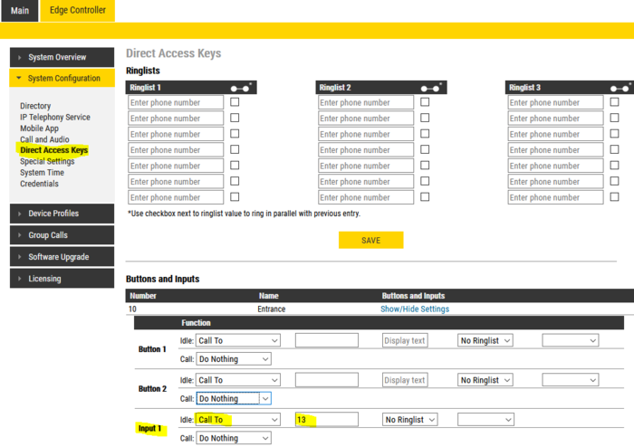
| + | *To configure the Input select '''Edge Controller''' > '''System Configuration''' > '''Direct Access Keys'''. <br> | ||
| + | *Select '''Show/Hide Settings''' on the station you want to configure. | ||
| + | *Configure the '''Input''' to '''Call To''', and enter the directory number to call when activated. | ||
| + | |||
| + | [[File:TouchLess Inp1 Edge.PNG|thumb|700px|left|Input 1 configured to call number 13 when triggered]] | ||
| + | <br style="clear:both;" /> | ||
| + | |||
| + | More details can be found on [[Direct Access Key & Ringlist Settings (Edge)|Direct Access Key Settings]]. | ||
| + | |||
| + | === Configuration in ICX-AlphaCom === | ||
| + | |||
| + | To configure the input to call a preconfigured number: | ||
| + | # Select '''Users & Stations''' | ||
| + | # Select the '''intercom station''' to which the touchless sensor is connected | ||
| + | # Open the '''DAK''' window | ||
| + | # Select the tab '''DAK 11-20''' | ||
| + | # On DAK 11 (= input 1(*)) enter the '''directory number''' to call when the input is activated | ||
| + | |||
| + | [[File:TouchLess ICX.png|thumb|700px|left|Input 1 configured to call number 13 when triggered]] | ||
<br style="clear:both;" /> | <br style="clear:both;" /> | ||
| + | (*) Input 1 - 6 on Turbine stations are mapped to DAK 11 - 16. | ||
| + | |||
| + | More information is found under [[Users & Stations (AlphaPro)#DAK|DAK programming]]. | ||
| + | |||
| + | ==Related Information== | ||
| + | * [http://www.zenitel.com/product/touchless-sensor Additional Documentation on Zenitel.com] | ||
| − | [[Category: | + | [[Category:Turbine Backboxes and accessories]] |
Latest revision as of 09:21, 24 October 2023
The Touchless sensor (item 2390020100) is an IR-sensor that connects to Zenitel IP stations, and is used to activate calls with gesture recognition instead of pressing the call button.
The sensor button is powered by 5 volts. Most Zenitel IP stations has a built-in 5V output which can be used to power the sensor button.
Contents
Highlights
- Input Voltage: 5V
- Available contacts: Normally Open & Normally Closed
- Sensor active time: 0,5 secs
- Operating distance: 15cm
- IP66
Connections
Connections are made to the switch using the supplied 5 pin plug.
Correct orientation of the plug is ensured by the connector locating guides.
Color code
- Red - +5 Volt supply
- Brown - 0 Volt supply
- Green - Normally Closed
- Blue - Common
- Purple - Normally Open
Typical Application
Use Case Examples
Touchless sensor - wiring example:
Configuration on IC-Edge
- To configure the Input select Edge Controller > System Configuration > Direct Access Keys.
- Select Show/Hide Settings on the station you want to configure.
- Configure the Input to Call To, and enter the directory number to call when activated.
More details can be found on Direct Access Key Settings.
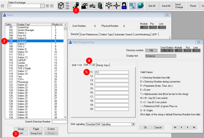
Configuration in ICX-AlphaCom
To configure the input to call a preconfigured number:
- Select Users & Stations
- Select the intercom station to which the touchless sensor is connected
- Open the DAK window
- Select the tab DAK 11-20
- On DAK 11 (= input 1(*)) enter the directory number to call when the input is activated
(*) Input 1 - 6 on Turbine stations are mapped to DAK 11 - 16.
More information is found under DAK programming.

