ICX-500/510 Gateway: Difference between revisions
From Zenitel Wiki
m (Asle moved page ICX-500 Gateway to ICX-500/510 Gateway) |
|
(No difference)
| |
Revision as of 12:28, 22 November 2023
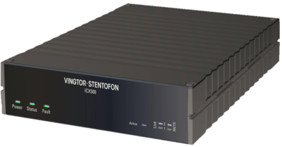
This article is applicable to the ICX-510 Gateway (item no: 100xxxxxx) and the ICX-500 Gateway (item no: 1002000100).
Connectors
| Connector | Type | Description |
| Ethernet | Eth0 / Eth1 | Two ethernet interfaces. The ICX-510 is equipped with two 1 Gbps ports, whereas the ICX-500 has two 100 Mbps ports. Each Ethernet port is equipped with LED indicators for link and activity. |
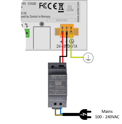
| Power | 24-48VDC | The unit is powered from a DC power supply with nominal voltage 24VDC or 48VDC (Min/Max: 20VDC-63VDC) |
| Console port RS232 | RJ45 | RS232 port is the RJ45 part of the dual connector RS232/USB. This is a console port for debugging purposes. Com parameters: 115.200 baud, 8 data bits, no parity, 1 stop bit. |
| USB | USB A USB micro-B |
The unit features one USB A and one USB micro-B connector |
| Fault Relay | 3 pole terminal block | Fault relay is used to indicate system status together with Fault LED |
| SD card | Micro SD card | Used for external storage or system recovery (Behind protection lid) |
| Factory Default Button | Tact switch | Used for resetting the unit to factory default settings (Behind protection lid) |
Power
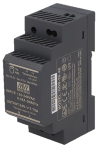
The IPS-AC1 from Zenitel is a 48VDC power supply, with input voltage range 85-264 VAC. It is designed for DIN-Rail mounting.
As an option one can use a locally provided power supply unit (PSU). The gateway must be powered by 24VDC or 48VDC. Recommended power rating of the PSU is minimum 24W (24V/1A or 48V/0.5A).
Network
The gateway has two RJ-45 ethernet ports for IP communication. Ethernet port 0 (Eth 0) is by default configured as a Management port, allowing connection to the embedded web server (ICX Web) and connection of the PC configuration tool AlphaPro. Default IP addresses:
- Eth0: Static IP address 169.254.1.5
- Eth1: Obtains IP address automatically (DHCP)
Start up and initial configuration
- Power up the gateway
- Watch the LEDs. During startup the Power LED and the Fault LED will be lit. The system uses approx. 20 seconds to start up. When up and running, the green status LED will start flashing.
- The unit comes with an embedded web server (ICX Web), which provides functions for system configuration, monitoring and upgrade. Initial connection is done by connecting a laptop to Eth port 0, open a web browser (e.g. Firefox or Chrome), and log on to the web server using IP address 169.254.1.5. (Default Username/Password = admin/alphaadmin).
- Upgrade the software of the unit to the latest version. Upgrade is done from the web interface of the gateway. This will ensure that the system has the latest features, bug fixes and security updates.
Status LEDs
The gateway has a number of status LEDs. The same LEDs are located both in front and at the rear side of the unit.
| LED | Description |
| Power | Steady green when power is applied |
| Status | Flashing green when the unit is running |
| Fault | Steady amber when the system reports an error. The LED will be lit during application or system reset, or if there is a temperature alarm. |
| Active | Steady blue when the gateway is operational. In a system with redundant servers, the Active LED will be lit on the operational gateway, and not lit on the standby gateway |
| Link | Steady green when the ethernet link 0 or 1 is up. There is one LED for each ethernet port |
| RX/TX | Flashing when receiving or transmitting data on ethernet port 0 or 1. |
Fault Relay
The fault relay will trigger when the system reports an error. In normal operation the relay is energized, which means it will also trigger on power outage.
Fault is reported:
- During Application or System reset
- If there is a Temperature alarm (Thresholds are 75C on PCB, 95C on CPU)
- If Power failure
User configuration
- AlphaPro is the Windows application used for configuration of the gateway. Configuration of user data, such as Directory Numbers, Direct Access Keys, Group Calls etc. is done from AlphaPro.

|
The gateway requires configuration tool AlphaPro ver. 12 or higher |
Factory Reset (cold boot)
The factory reset button is used to restore the unit to factory settings. The factory reset (cold boot) button is located on rear side, behind the same protection lid as the micro SD card.
Two different procedures are available:
Complete:
- Load default intercom database
- Reset all IP settings to default (E.g. IP addresses and Filters). Eth0 will get IP address 169.254.1.5, subnet mask 255.255.0.0.
- Press an hold the "Factory Default" button
- Power up the unit while the button is pressed
- Keep the button pressed for approx. 5 sec., then release it

|
|
Intercom Configuration only:
- Keep the IP settings
- Load default intercom database
- Power up the unit
- Wait for 5 sec., then press and hold the “Factory Default” button
- Keep the button pressed until the Status LED is flashing green or the fault relay is clicking (Approx. 10 sec)
Factory reset can also be done from the ICX web interface: System Maintenance > System Recovery > Load Factory Defaults
Software upgrade
- It is highly recommended to Upgrade the software of the gateway to the latest version. Upgrade is done from the web interface of the gateway. This will ensure that the system has the latest features, bug fixes and security updates.
Accessing the SD Card and Factory Default button
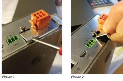
The SD Card and the Factory Default button are located behind a protective lid.
- Locate the lid, it is between the fault relay and the power connector
- Loosen the screw, but don't remove. Tool: Torx T6.
- Lift the lid out at the bottom side (Picture 1)
- Remove the lid (Picture 2)
- The SD card slot and factory default button are now accessible
- Replace the lid in reverse order
Dimensions & Mounting
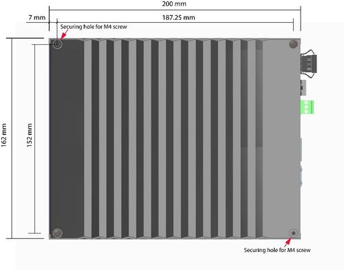
Dimensions
Wall/Shelf Mounting
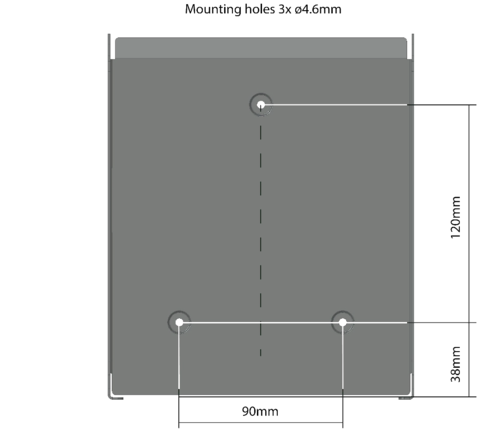
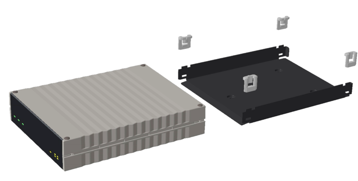
Using the IA-MB1 mounting bracket (item no: 1002500020), the unit can be mounted on any flat surface such as a wall or shelf. The following procedure is for a mounting on a wall as an example.
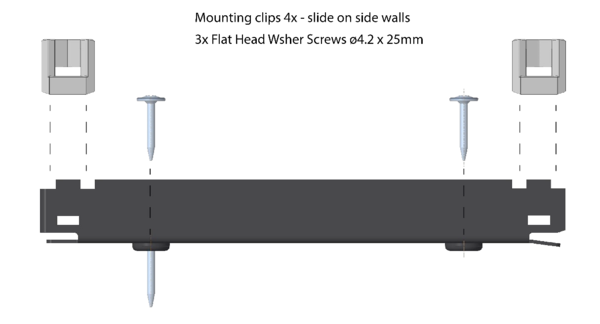
1. Mount the bracket to the wall using the 3 screws provided.
2. Slide the 4 mounting clips into the side walls of the bracket.
3. Slide the unit into the bracket
To have logo and connection annotations in the correct viewing orientation, you may slide the unit top or bottom down into the bracket depending on whether it is mounted on a wall, desk or shelf.
Rack Mounting
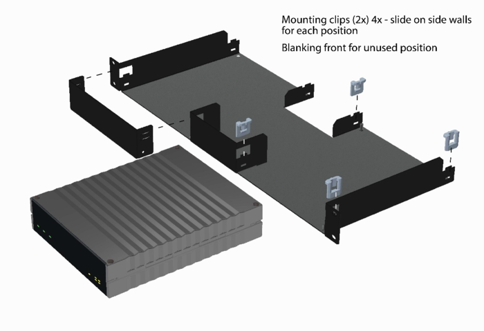
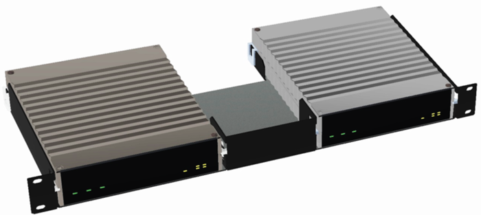
Using the IA-RS1 Rack Shelf (item no: 1002500010), two units can be mounted side by side in a 19" 1HU rack.
1. Slide the 4 mounting clips into the side walls of the rack shelf.
2. Slide the unit into the rack shelf.
3. Use the 2 countersunk type M4x8 screws to secure the unit to the rack shelf via the 2 diagonally positioned securing holes.
The securing holes can also be used to mount the unit to a shelf other than the IA-RS1. Note that the maximum insertion depth is 6 mm.
Additional information
- Datasheet and specifications: Additional Documentation on Zenitel.com

