IP Desktop - Video Module Configuration: Difference between revisions
From Zenitel Wiki
(→System) |
No edit summary |
||
| (9 intermediate revisions by 3 users not shown) | |||
| Line 1: | Line 1: | ||
{{ | {{AEIPS}} | ||
{{obsolete}} | |||
This product can be replaced by [[ITSV-4]] or [[ITSV-5]] | |||
[[File:1408001635.jpg|thumb|250px|IP Desktop Station with Video Display - 1408001635]] | [[File:1408001635.jpg|thumb|250px|IP Desktop Station with Video Display - 1408001635]] | ||
This article describes how to configue the '''LCD Video module''' of the IP Desktop Video Station. The Video Module has its own IP address, separate from the audio part of the station. | This article describes how to configue the '''LCD Video module''' of the IP Desktop Video Station. The Video Module has its own IP address, separate from the audio part of the station. | ||
| Line 52: | Line 55: | ||
* '''Passcode required''': Activates or deactivates the requirement for a passcode authentication to access this camera via the "Cam Select" menu in the LCD screen | * '''Passcode required''': Activates or deactivates the requirement for a passcode authentication to access this camera via the "Cam Select" menu in the LCD screen | ||
* '''Allocation active?''': Enables or Disables this camera. '''Must be enabled''' to see video image from this camera. | * '''Allocation active?''': Enables or Disables this camera. '''Must be enabled''' to see video image from this camera. | ||
=== Configuration for Turbine stations TCIV+ === | |||
* Applicable for Turbine models [[TCIV-2]], [[TCIV-3+]], [[TCIV-5+]] and [[TCIV-6+]] | |||
* For TCIV+ one must define a new Camera Type, using the URL: '''/mjpg/video.mjpg''' | |||
* Camera User and Camera Password must be entered. Default username and password are '''admin/alphaadmin''' | |||
* Port number 80 is the default port used for video in the TCIV station. If needed, port number 8090 can be used for HTTP MJPEG video stream. The port number must be enabled in the Firewall of the station. | |||
* The resolution will automatically adjust to 320x240. | |||
[[File:Ip desk video tciv+.png|thumb|left|500px|Configuration for TCIV+ camera]] | |||
<br style="clear:both;" /> | |||
=== Configuration for Turbine stations TCIV === | === Configuration for Turbine stations TCIV === | ||
* Applicable for Turbine models [[TCIV-2]], [[TCIV-3]] and [[TCIV-6]] | * Applicable for Turbine models [[TCIV-2]], [[TCIV-3]] and [[TCIV-6]] | ||
* For TCIV one must define a new Camera Type, using the URL: ''':8090/mjpg/video.mjpg''' | * For TCIV one must define a new Camera Type, using the URL: ''':8090/mjpg/video.mjpg''' | ||
* Port number 8090 is the default port used for video in the TCIV station | * Port number 8090 is the default port used for video in the TCIV station. The port number is configurable in the [[Turbine Video Settings|TCIV station]]. | ||
[[File:IP Desktop TCIVCamera.PNG|thumb|left|500px|Configuration for TCIV camera]] | [[File:IP Desktop TCIVCamera.PNG|thumb|left|500px|Configuration for TCIV camera]] | ||
<br style="clear:both;" /> | <br style="clear:both;" /> | ||
| Line 105: | Line 118: | ||
After tapping the second cross, the calibration process will be completed. | After tapping the second cross, the calibration process will be completed. | ||
== How to manually select video image == | |||
Touch on the upper part of the LCD screen to get the Option Menu. | |||
[[File:VideoOptionMenu.PNG|thumb|left|300px|The Option menu]] | |||
<br style="clear:both;" /> | |||
At the bottom of the option screen there are four buttons for the following functions: | |||
[[File:CamSelect.PNG|40px|left]] | |||
'''Cam Select:''' Press this button to get a list of defined cameras. A touch on a camera entry shows the camera stream for 60 seconds. A touch on the screen during this 60 seconds will stop the stream and jump back to "Cam Select" screen. If the camera is configured to require Passcode authentication, you need to enter the code to access the video stream. | |||
<br style="clear:both;" /> | |||
[[File:CamSwtch.PNG|40px|left]] | |||
'''Enable/Disable Cam switching:''' If more than one camera has been allocated to a remote station the display will switch between the allocated cameras every 5 seconds. This feature can be enabled/disabled here. | |||
<br style="clear:both;" /> | |||
[[File:CamScreensaver.PNG|40px|left]] | |||
'''Enable/Disable Screensaver; avoid total switch off:''' If this function is enabled, the Screensaver does not switch off the display after a period of inactivity. Only the Backlight is dimmed. | |||
<br style="clear:both;" /> | |||
[[File:CamHome.PNG|40px|left]] | |||
'''Back to Main Screen:''' A push on this button will jump back to the Main screen. | |||
<br style="clear:both;" /> | |||
== Troubleshooting == | |||
'''Observation:''' Desktop Video Station flash yellow and red, does not display text, and will not show video on the screen (even though registered). Audio is functioning normally as calls can be made and received | |||
'''Cause:''' The IP station is most likely in “Debug” mode, thus set to the wrong baud rate for the serial communication between the IP Station and the Video Module. 115200 baud is used for debugging, while 38400 baud is for normal operation. | |||
'''Fix:''' Use a webbrowser and enter '''[station IP address]/goform/zForm_misc'''. Set '''Baudrate''' to ''38400'', and click '''RS232 for application'''. | |||
Note that there is no feedback on current settings. Remember to perform application reset to make the changes take effect. | |||
[[File:IP Video Desk Trouble1.PNG|thumb|left|400px]] | |||
<br style="clear:both;" /> | |||
[[Category:Video]] | [[Category:Video]] | ||
[[Category:INCA Station Configuration Guide]] | [[Category:INCA Station Configuration Guide]] | ||
Latest revision as of 13:02, 3 January 2025
This product can be replaced by ITSV-4 or ITSV-5
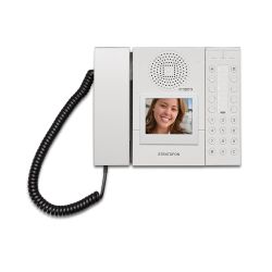
This article describes how to configue the LCD Video module of the IP Desktop Video Station. The Video Module has its own IP address, separate from the audio part of the station.
The default IP address of the Video Module is 169.254.1.101.
Login
The Video Module has its own IP address, and is configured separately from the station.
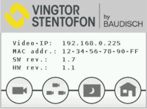
- Touch the upper part of the LCD touch screen for a few seconds to read the IP address.
- Enter the IP address (e.g. "169.254.1.101") in a web browser and log on the the video part of the desktop station.
- Enter user name (default: admin) and password (default: alphaadmin)
Network
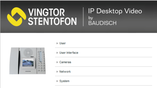
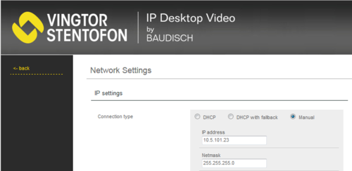
From the main menu, click on Network, and configure the station to use DHCP (obtain an IP address automatically) or Manual (Static IP address).
Cameras
The video is streamed in MJPEG format directly from the camera to the Video Module. The server to which the station is registered is not involved in the video stream. The cameras must have a static IP address.
The directory number of the Video Door Station must be defined in camera allocation list, together with the URL of the camera. When a call is received, the station will look up in this camera allocation list, and find the correct URL for the associated camera.
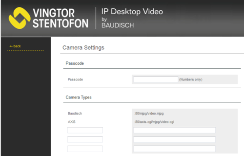
To access the camera allocation table, select Cameras from the main menu. Up to 80 cameras can be configured in this table.
Passcode
By using the menus on the LCD touchscreen, it is possible to view a camera image from idle, without any calls being active. The Passcode is an up to 10 digit long numeric code for restricting the access to the camera image. If Passcode is required or not, is a setting per camera in the Camera Allocation table.
Camera Types
There are two predefined Camera Types, Baudisch and Axis. In addition there are 3 empty fields in which one can define additional camera types and their URL. This is the case when using TCIV stations (Turbine with Video).
Camera Allocation
Use the left (<) and right (>) arrows to step up and down in the Camera Allocation table. Up to 80 cameras can be defined.
- Name: Any text (optional). The text is displayed in the LCD screen during ringing and while in conversation, and in the "Cam Select" menu when accessing video from idle. If this field is blank, the name received in the Caller ID will be displayed in the LCD screen during a call.
- AlphaCom Node Number:
- When used in AlphaCom mode: Enter the node number of the AlphaCom. Normally value "1".
- When used in SIP or Pulse mode: Enter "0".
- AlphaCom Directory Number:
- When used in AlphaCom mode: Enter the directory number of the door intercom with camera.
- When used in SIP or Pulse mode: Enter "0".
- SIP ID:
- When used in AlphaCom mode: Leave the field blank
- When used in SIP or Pulse mode: Enter the directory number of the door intercom with camera.
- Camera IP: The IP address of the camera allocated to the intercom unit
- Camera Type: Choose the camera type
- Camera User: Type in the username to access the camera stream (optional)
- Camera Password: Type in the password to access the camera stream (optional)
- Passcode required: Activates or deactivates the requirement for a passcode authentication to access this camera via the "Cam Select" menu in the LCD screen
- Allocation active?: Enables or Disables this camera. Must be enabled to see video image from this camera.
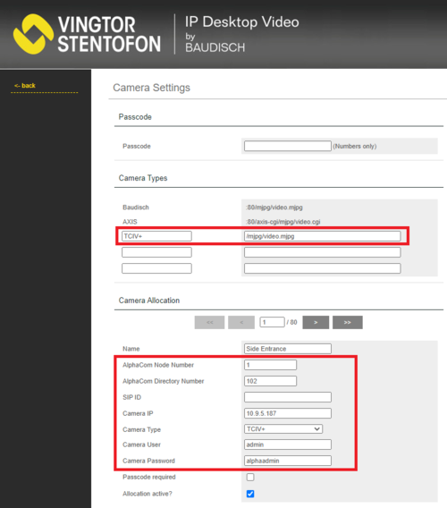
Configuration for Turbine stations TCIV+
- Applicable for Turbine models TCIV-2, TCIV-3+, TCIV-5+ and TCIV-6+
- For TCIV+ one must define a new Camera Type, using the URL: /mjpg/video.mjpg
- Camera User and Camera Password must be entered. Default username and password are admin/alphaadmin
- Port number 80 is the default port used for video in the TCIV station. If needed, port number 8090 can be used for HTTP MJPEG video stream. The port number must be enabled in the Firewall of the station.
- The resolution will automatically adjust to 320x240.
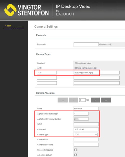
Configuration for Turbine stations TCIV
- Applicable for Turbine models TCIV-2, TCIV-3 and TCIV-6
- For TCIV one must define a new Camera Type, using the URL: :8090/mjpg/video.mjpg
- Port number 8090 is the default port used for video in the TCIV station. The port number is configurable in the TCIV station.
- The TCIV camera must be configured to use MJPG video format and resolution 320 x 240. Log on to the TCIV station, select Video Settings, set "Video Mode" = MJPG and "Resolution and fps" = 240P 15fps.
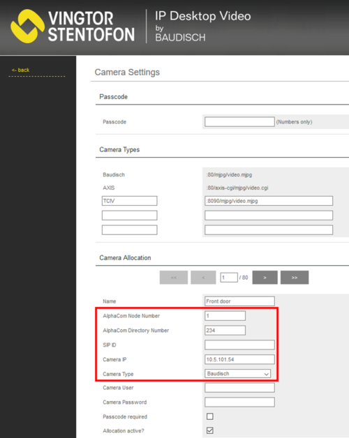
Configuration for IP Video Door Station - 1401110100
- The IP Video Door Station - 1401110100 uses the predefined Camera Type Baudisch:
- The CP-CAM camera must be set to use resolution 320 x 240. Log on to the camera, and, select System Settings > Camera, and set "Mode" to QVGA (320 x 240)
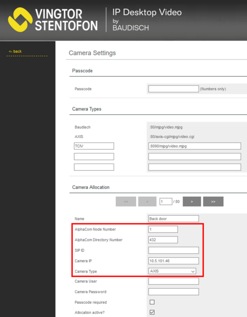
Configuration for IP Video Door Station - 1401110200
- The IP Video Door Station - 1401110200 uses the predefined Camera Type Axis:
- The Axis camera should be set to use resolution 320 x 240.
- Log on to the Axis camera (default username: root, password: 1234)
- Select Setup > Video > Video Stream and change the resolution to 320 x 240 pixels.
System
- Camera Allocation: Upload or download the camera allocation list.
- Settings: Upload or Download the settings of the LCD screen (including the camera allocation).
- Factory Reset: Resets the LCD screen to factory settings. Resets the LCD screen only.
- Firmware update: Upload new firmware to the LCD screen.
User Interface
Select User Interface from the main menu to change the behavior of the user interface on the LCD screen.
- Screensaver: Define timers and brightness for the screensaver.
- Text overlay during video: Here you can define properties of the overlay text in the LCD screen during ringing and connected call.
User
Select User from the main menu to change the username and password for the access to the web interface.
Touchscreen Calibration
The touchscreen calibration display is activated by pressing and holding the screen during startup when the splash screen is displayed or via the web interface under menu option System
When the calibration screen is shown, tap the displayed cross and another cross will be displayed.
After tapping the second cross, the calibration process will be completed.
How to manually select video image
Touch on the upper part of the LCD screen to get the Option Menu.
At the bottom of the option screen there are four buttons for the following functions:
Cam Select: Press this button to get a list of defined cameras. A touch on a camera entry shows the camera stream for 60 seconds. A touch on the screen during this 60 seconds will stop the stream and jump back to "Cam Select" screen. If the camera is configured to require Passcode authentication, you need to enter the code to access the video stream.
Enable/Disable Cam switching: If more than one camera has been allocated to a remote station the display will switch between the allocated cameras every 5 seconds. This feature can be enabled/disabled here.
Enable/Disable Screensaver; avoid total switch off: If this function is enabled, the Screensaver does not switch off the display after a period of inactivity. Only the Backlight is dimmed.
Back to Main Screen: A push on this button will jump back to the Main screen.
Troubleshooting
Observation: Desktop Video Station flash yellow and red, does not display text, and will not show video on the screen (even though registered). Audio is functioning normally as calls can be made and received
Cause: The IP station is most likely in “Debug” mode, thus set to the wrong baud rate for the serial communication between the IP Station and the Video Module. 115200 baud is used for debugging, while 38400 baud is for normal operation.
Fix: Use a webbrowser and enter [station IP address]/goform/zForm_misc. Set Baudrate to 38400, and click RS232 for application.
Note that there is no feedback on current settings. Remember to perform application reset to make the changes take effect.


