IP Video Door Station - 1401110200: Difference between revisions
From Zenitel Wiki
| Line 10: | Line 10: | ||
== IP Station Configuration == | == IP Station Configuration == | ||
See article: [[ | See article: [[IP_Station_Configuration#Configuration_in_IP-StationWeb]] | ||
==Reset to factory settings== | ==Reset to factory settings== | ||
Revision as of 11:22, 5 November 2014
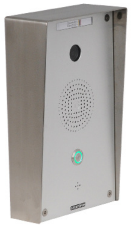
The STENTOFON Vandal Resistant IP Video Station (item 1401110200) is tough, durable and resilient, and designed for use in the harshest of environments. The station is typically used as a communication, information or emergency point and connects directly to the IP network making it easy to deploy – anywhere and at any distance. Designed for CCoIP® the station offers a set of critical communication features such as integrated firewall, group call, call priority and over-ride, to name just a few. This enables you to deliver instant, efficient and secure voice, video and data services in an IP environment.
Installation
See article: IP Station Installationxx
Station Board Connectors and LED Indications
See article: IP Station Board Connections and Indications
IP Station Configuration
See article: IP_Station_Configuration#Configuration_in_IP-StationWeb
Reset to factory settings
See article: IP Station Restore Factory Defaults
Software Upgrade
See article: IP Station Software upgrade
Dimensions
See article: IP Stations Dimensions and Mounting Instructions
Configuration
CCoIP Station
The station must be given an IP address, either static or one provided by a DHCP server. In addition the IP address of the AlphaCom and the directory number must be set. This is all done in the inbuilt webserver.
For more details, please see: IP Station IP and Server configuration
Camera
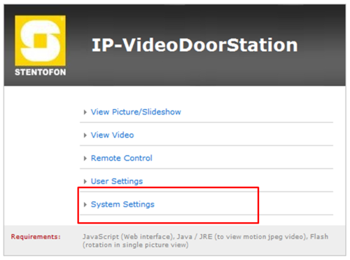
Connect to the camera using a webbrowser on default IP address 169.254.1.101.
In the menu that appears, click System Settings, and you will be asked to login:
Username: admin
Password: 1234
Set to factory default:
CP-Cam Factory Reset
This should be carried out only by experienced technicians. The customer is liable for damages caused by improper opening of the housing.
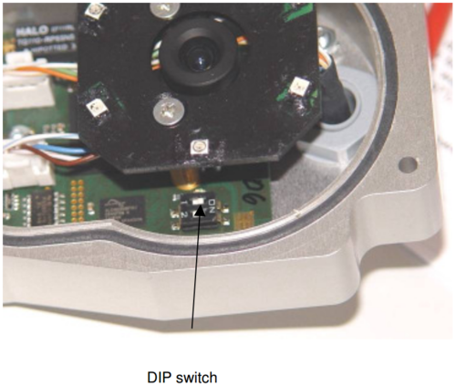
If the entered IP address is unknown, it is possible to reset the address to 169.254.1.101 using the DIP switch. To proceed, the unit must be opened.
Note: A change of the IP address is made via the web interface of the CP-CAM.
The procedure is as follows:
- 1. Open the CP-CAM so the two DIP switches are accessible ( see picture ).
- 2. Note the switch position and then turn both switches to „OFF“.
- 3. Connect PC with the IP number range 169.254.1.xxx and set the desired IP address in the web interface.
- 4. Turn switch positions back to original positions.
- 5. Close housing properly.
Axis Factory Reset
To restore the factory settings, proceed as follows:
- 1. Disconnect the camera from the power supply and ethernet.
- 2. Remove the four screws securing the rear cover and remove it.
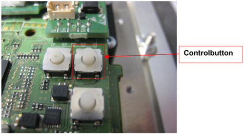
- 3. Keep the Control button pressed while you restore the power supply.
- 4. Hold down the button for about 15 seconds until the status LED is yellow flashing.
- 5. Release the Control Button. The process is complete when the status LEDs light up green.
If no DHCP server is active on your network the new default IP is 192.168.0.90.
The new default user is root with password pass
Setup with STENTOFON Video Display Station
To configure the STENTOFON Video Display Station please see: IP Desktop Station with Video Display - 1408001635
This chapter describes the steps for configuring the CP-Cam:
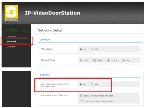
From the Main Menu select System Settings > Network
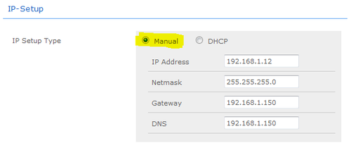
- 1. Under section IP-SETUP, set IP-SETUP Type to Manual
- 2. Enter a static IP adresss, Netmask, Gateway and DNS
- 3. Under section System, set Authentication required for Picture/Video to No
- 4. Click Save Changes at the bottom of the page
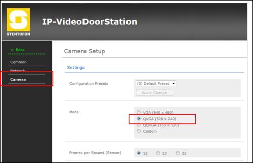
From the Main Menu select System Settings > Camera
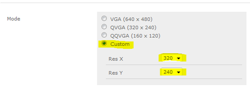
- 1. Under section Settings, set Mode to Custom
- 2. Set Res X to 320
- 3. Set Res Y to 240
- 4. Under section Settings, set Frames per Second (Sensor) to 15
Setup with 3rd party Video devices
SNOM IP Phones
The video image of the IP Video Door Station can be displayed on a Snom IP phone display. Following possibilities can be realized:
- Manual video image. The video image of the IP Video Door Station can be activated and ended by key press.
- Pop up video image. The video image of IP Video Door Station is shown automatically on an incoming call and end automatically when the communication is finished.
Conditions for displaying a video image by an incoming call:
- Compatible Snom phone (models 820, 821, 760)
- Registration on an AlphaCom, PULSE server or SIP-server.
- Snom firmware must be version 8.7.4.5t.
AlphaCom configuration
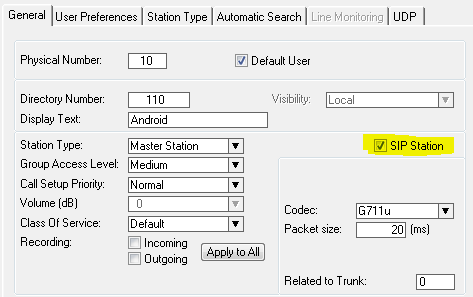
The Snom phone must be configured as a SIP User in AlphaPro, Users & Stations. See article SIP phone as station for details.
Firmware update of Snom phone
The firmware of the Snom phone must be uploaded using a TFTP server. Upgrade procedure:
- Download the software 8.7.4.5t from the AlphaWiki download site
- Unzip the file. Remember in which folder you stored the file
- Start a TFTP server, and browse to the folder which contains the file
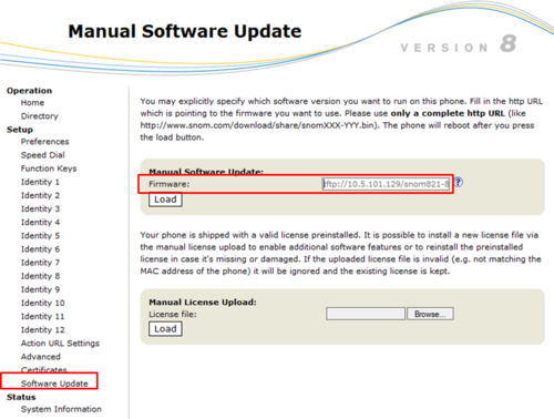
- In the Snom webinterface, select Software Update and enter address tftp://[TFTPServer]/[file name], where [TFTPServer] = IP address of PC running the TFTP server and [file name] is the name of the downloaded .bin file. Example: tftp://10.5.101.129/snom821-8.7.4.5t-SIP-r.bin.
- Select Load, and watch the progress on the display of the Snom phone
Network and SIP account in Snom phone
Factory default of the phone is done from the phones keyboard by pressing:
- The button Menu
- 5 - Maintenance
- 4 - Reset Values
- Enter default password 0000. The phone will restart.
Follow the display setup wizard to set:
- Language
- Time Zone
- Tone scheme
- SIP Account = Directory number in AlphaCom
- Registrar = IP address of AlphaCom
- Select DHCP or enter IP settings of phone
The phone must be rebooted after this.
SIP account settings can be changed in Identity 1 in web access. IP settings are changed in Advanced -> Network.
Codec settings
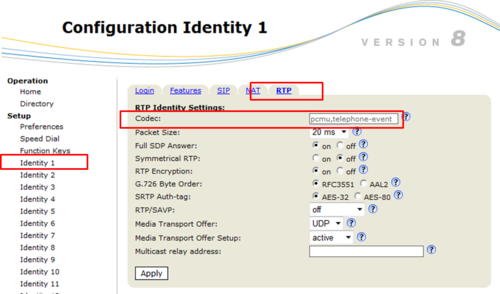
Codec must be changed to G.711u-law (pcmu) and the internal "telphone event".
In Identity 1 -> RTP, set the codec to: "pcmu,telephone-event", remove all other codecs:
Pop up video image
The screen display in the XML-Mini-Browser of Snom IP phones can be started and ended automatically. The following settings are necessary.
Configuration in Snom Phone
Firmware version 8.7.4.5t-SIP-r for the Snom phones 820, 821, 760 is required to get video pop up.
The IP Video Door Station(s) must be defined in the Directory of the Snom phone.
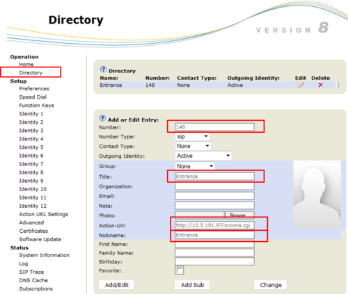
In the web interface of the phone, select Directory in the menu, and enter the following parameters:
- Number: The directory number of the IP Video Door Station, as entered in AlphaPro, Users & Stations.
- Title: Enter any text
- Action URL: http://<IP adress of the camera>/snoma.cgi. For example http://10.5.101.97/snoma.cgi
- Nickname: Enter any text
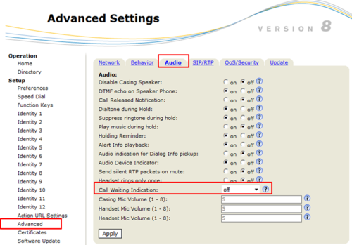
Set "Call Waiting Indication" to "Off":
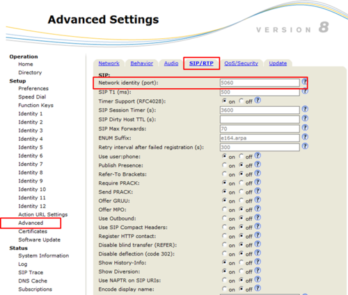
Set SIP port to 5060:
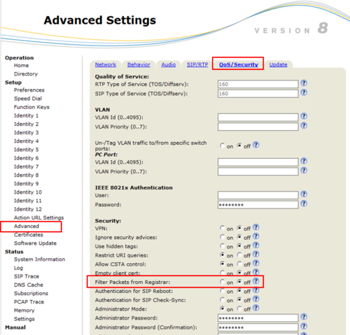
Disable "Filter packets from Registrar":
Configuration of the camera
In the camera the authentication for the image/video display has to be deactivated. Log on to the camera (default username: admin, password: 1234). Under System Settings->Network->System, change the "Authentication required for Picture/Video" to "No".
Set the resolution to match the video display of the Snom phone, 320 x 240 pixels:
Operating the Door Opening relay
During conversation with the IP Video Door Station the integrated relay of the door station can be operated by pressing digit 6 on the Snom phone. The Snom phone uses DTMF by RFC2833 by default, which is supported by AlphaCom, so no settings are required in the phone.
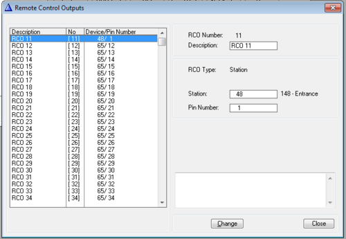
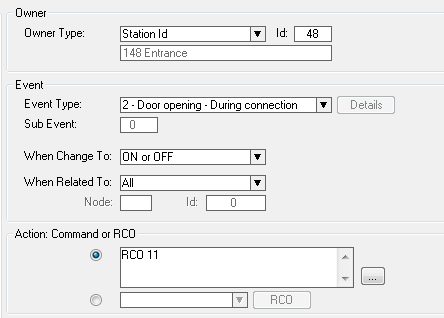
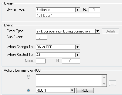
In AlphaCom the relay must be mapped to a logical RCO, and an "Door Opening" event created to trigger this RCO.
To map a logical RCO to the relay of the IP Station, select Exchange & System -> RCO. Pick a free RCO, select Change and set the RCO Type = Station, enter the physical number of the IP Station, and set pin number = 1. In the example below the relay of IP Video Door station 48 (directory number 148) is mapped to RCO 11.
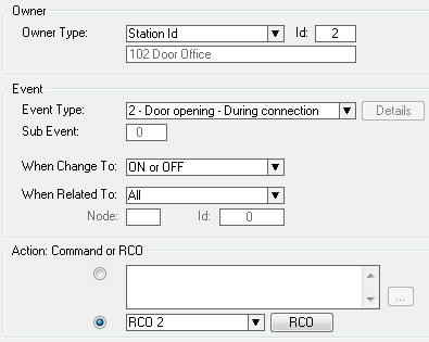
Create a "Door Opening" event with the IP Video Door Station as the event owner. Select Exchange & System -> Events, and Insert a new event with the following properties:
For connection details, see article: IP Station Board Connections and Indications
Manual video image (Optional)
The video image of the IP Video Door Station in the Snom IP phones can be started and ended manually by pressing a function key. With this feature the video image can be displayed without setting up a conversation.
Configuration of the Snom phone
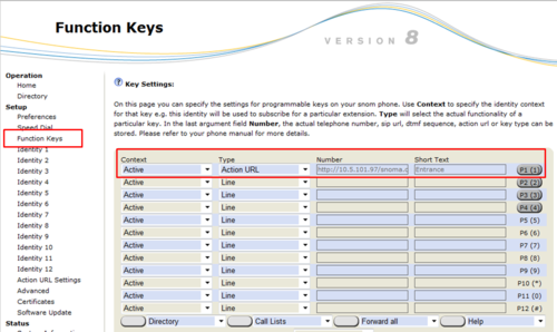
In the web interface of the phone, select Function Keys in the menu, and enter the following parameters:
- Context: Active
- Type: Action URL
- Number: http://<IP adress of the camera>/snoma.cgi. For example http://10.5.101.97/snoma.cgi
- Short text: Enter any text
How to use
- Start video image: The video image is started by pressing the programmed key.
- End video image: The video image is ended by pressing the "X-key".
Authentication
If the access of the camera is to be password protected, the following adjustments are necessary.
Configuration of the Snom phone
In the web interface of the phone, select Function Keys in the menu, and enter the following parameters:
- Context: Active
- Type: Action URL
- Number: http://<User name>:<Password>@<IP adress of the camera>/snoma.cgi. If for example username is "viewer" and the password is "1234", enter http://viewer:1234@10.5.101.97/snoma.cgi
- Short text: Enter any text
Configuration of the camera
In the camera the authentication for the image/video display has to be activated. Under System Settings->Network->System, change the "Authentication required for Picture/Video" to "Yes".
DIVUS Videophone
Android
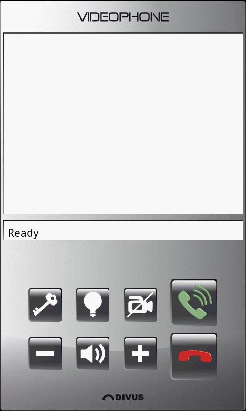
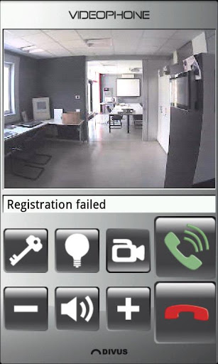
The Divus Videophone app for Android give the opportunity to receive calls from the IP Video Door Station. In addition it shows a live video stream from the inbuilt camera. The video stream is active as long as the call is active. It is even possible to view the video without setting up a call. The app also has a dedicated button for door opening.
The app can be downloaded from this site: https://play.google.com/store/apps/details?id=eu.divus.videophone&hl=en
Install and run the app on your Android device.
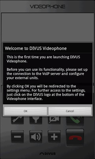
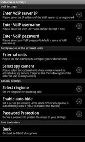
When the app starts it immediatly wants to be configured. The following parameters must be entered:
- VoIP Settings: Enter the IP address of the AlphaCom
- Enter VoIP username: The directory number the mobile should register as in the AlphaCom
- Enter VoIP password: The directory number the mobile should register as in the AlphaCom
- Enter VoIP port: Leave as default (5060)
- Enable re-registration: Enable
- Registration timeout: Leave as default (1440)
- Phonebook: se next
- Select spy camera: Here it is possible to define which External Unit (camera) to watch without making a call to that particular station.
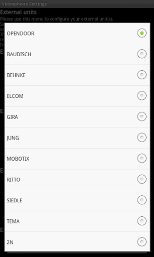
In the Phonebook menu select External Units to configure. Under External Unit 1 select Baudisch from the drop down list. Then:
- VoIP ID: The directory number of the IP Video Door Station
- Main camera - IP: The IP address of the camera in the IP Video Door Station
- Display name: A descriptive name to be shown in the video image tohether with the video stream
- Optional: Enable the QuickDial button (allows to call the IP Video Door Station directly, like a DAK)
- Click Back on the top to save settings and return to the previous menu.
- Scroll down to the bottom and click Back to save and return to the Divus Videophone main window.
The Divus Videophone should now register and show Ready.
Make a call either by clicking the green phone symbol to show the keypad and dial manually, or by clicking the optional QuickDial button (if configured).
Click the red phone symbol to hang up.
Clicking the camera symbol allows to show the video stream from a preselected camera without making a call.
The + and - symbols is used to adjust volume up or down, while the speaker symbol in between is used for muting the speaker.
The key symbol can be used to unlock the door remotely (requires AlphaCom configuration).
For the AlphaPro configuration, please see AlphaPro
PC
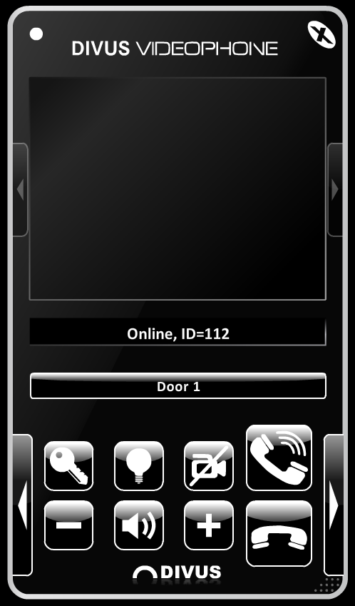
The licensed Divus Videophone software for Windows PC gives the opportunity to receive calls from the IP Video Door Station. In addition it shows a live video stream from the inbuilt camera. The video stream is active as long as the call is active. It is even possible to view the video without setting up a call. The software also has a dedicated button for door opening. If the Divus Vdeophone is minimized it will automatically pop up when there is an incoming call, and it will stay up during the length of the conversation. When the conversation is finished it stays up for three more minutes, before automatically minimizing.
Please contact Divus to obtain the software.
Install and run the software on your Windows PC.
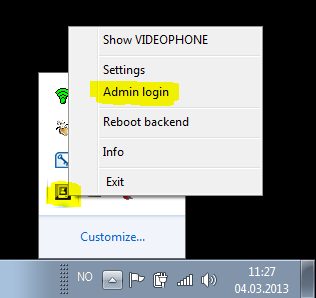
Before configuring you must log in. This is achieved by right clicking on the Divus icon in the system tray (lower right corner).
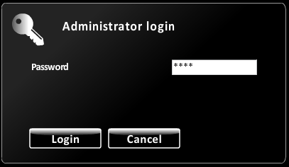
Select Admin login:
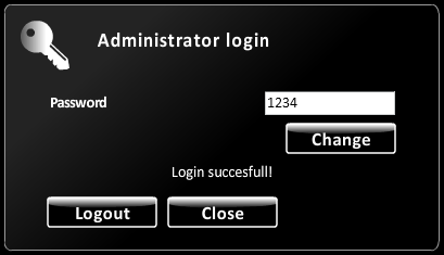
Enter the default password 1234, and click Login.
Enter the configuration menu by clicking on the lower left arrow in the main window.
Select the VoIP button.
In the VoIP settings configure:
- Server IP: The AlphaCom IP address.
- Username: The directory number that you want the Divus Videophone to register as in the AlphaCom.
- The remaing fields are automaitcally filled out with the same as you write in the Username field, and should be left untouched.
- Click Save, the software will "reboot", and should register to the AlphaCom.
- Click the VoIP button again to return to the main menu.
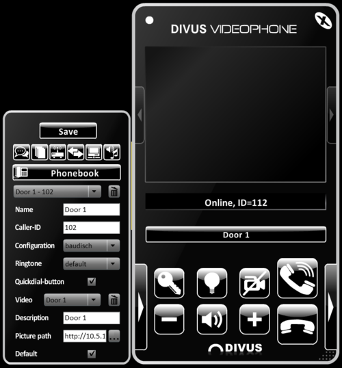
Select the Phonebook button.
In the Phonebook create a new entry by clicking the dropdown box and selecting -New entry-.
- Name: Enter a descriptive name that will be shown on the optional Quickdial-button if used. For example "Door 1".
- Caller-ID: Enter the directory number of the IP Video Door Station.
- Configuration: Scroll through the dropdown list and select baudisch.
- Quickdial-button: Optional: Select this option if you want to have a speed dial button (DAK) to call the IP Video Door Station without dialing the number manually.
- Video: Click the dropdown box and select -New video-.
- Name: Enter a descriptive name that will be shown together with the video during streaming. For example "Door 1".
- Picture path: Use the browse button to select a still image to associate with the station. If the station has a camera enter: http://<the camera IP address>/jpg/image.jpg.
- Default: If this box is enabled it will make it possible to view this image/videostream without setting up a call.
- Click Save, the software will "reboot".
Close the menu by clicking on the lower left arrow in the main window.
Click the optional QuickDial button (if configured) to call the preconfigured Door 1 in the above example.
To make a manual call, click the lower right arrow to open the keypad. Dial the desired number and call by clicking the top phone symbol.
Click the lower phone symbol to hang up.
Clicking the camera symbol allows to show the video stream from the camera(s) without making a call. Must be enabled in the Phonebook settings.
The + and - symbols is used to adjust volume up or down, while the speaker symbol in between is used for muting the speaker.
The key symbol can be used to unlock the door remotely (requires AlphaCom configuration).
For the AlphaPro configuration, please see AlphaPro
AlphaPro
The Divus Videophone for Android and Windows PC must be configured in the AlphaCom as a SIP station.
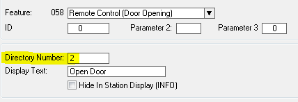
The Divus Videophone sends digit 2 when pressing the key symbol. To make this operate the door lock from AlphaCom the default door opening digit 6 must be changed. In Directory&Features locate feature 058 - Remote Control (Door Opening) and change the directory number from 6 to 2. You will get a warning that this is overwriting a different feature, but this must be accepted to make it work. The other feature can be recreated as digit 6 after.
Finally, create an ordinary Door Opening Event in the Event Handler.
PhonerLite SIP Client
The PhonerLite SIP Client gives the opportunity to receive calls from the IP Video Door Station. In addition it shows a live video stream from the inbuilt camera. The video stream is active as long as the call is active.
The app can be downloaded from this site: http://phonerlite.de/index_en.htm
Install and run the app on your Windows PC.
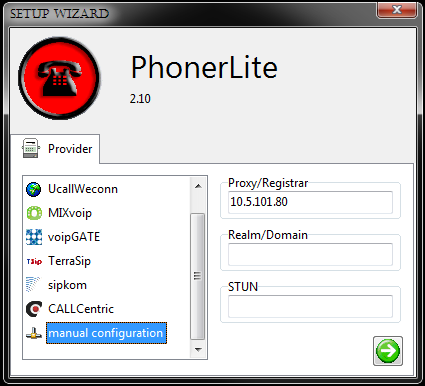
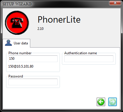
When the app starts it immediatly wants to be configured. The following parameters must be entered:
- Proxy/Registrar: Enter the IP address of the AlphaCom
- Phone number: The directory number the SIP Client should register as in the AlphaCom
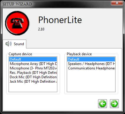
- Select the wanted audio devices
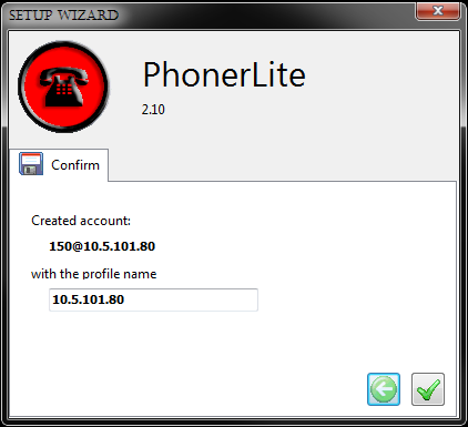
- Confirm the settings
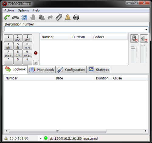
The PhonerLite SIP Client should now register and show Ready.
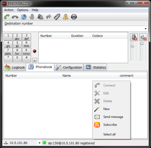
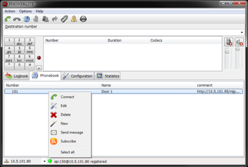
Select the Phonebook by clicking the Phonebook tab.
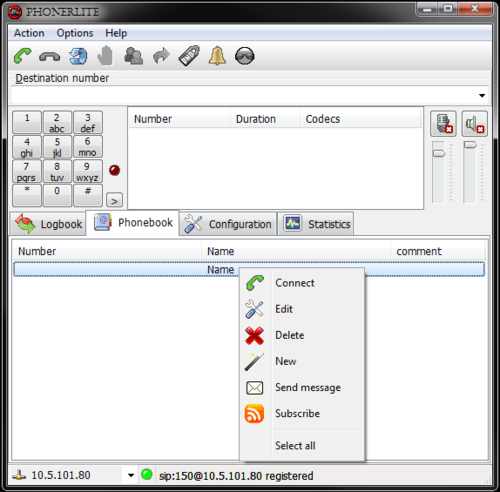
- Right click the Name tab and select New
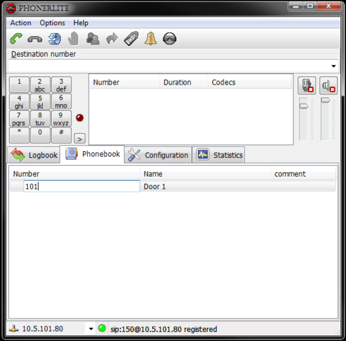
- Right click the new line under Name and select Edit. Type in a descriptive name of the contact:
- Right click the new line under Number and select Edit. Type in the directory number of the contact:
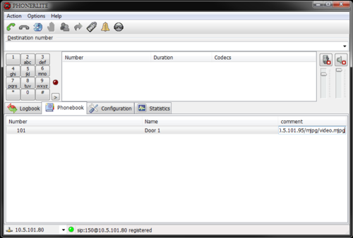
- Right click the new line under comment and select Edit. Type in the URL for the IP Video Door Station camera: (http://<ip address>/mjpg/video.mjpg)
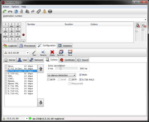
Select the Configuration tab, and then the Codecs tab. Disable all codecs except G.711 µ-Law. complete the configuration by clicking the Save disk symbol:
Make a call either by dialing manually on the keypad, or by rightclicking the wanted contact in the phonebook and selecting Connect.
Click the red phone symbol to hang up.
AlphaPro
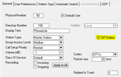
The PhonerLite SIP Client for Windows PC must be configured in the AlphaCom as a SIP station.
The PhonerLite SIP Client supports SIP INFO and can perform door opening the standard way.
Milestone
It is assumed that a Milestone XProtect system is already installed and up and running. The latest Milestone XProtect Professional and Smart client can be downloaded from Milestonesys.com.
The version used in the examples that follows is XprotectPro V8.1a
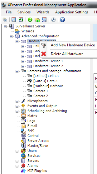
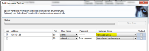
Open the XProtect Professional Management Application by double clicking the desktop icon. Expand the mennu tree strcture and right click Hardware Devices. Select Add New Hardware Device
Choose Manual as the hardware detection method.
- 1 Enable Use
- 2 Type in the IP address of the camera in the Address field
- 3 Select username admin from the dropdown box under User Name
- 4 Enter the default IP Video Door Station camera password: 1234 in the Password field
- 5 In the Hardware Driver dropdown box, scroll down and select Universal Driver
- 6 Repeat for 1-5 the next camera(s)
- 7 Click Next, followed by Finish in the next window.
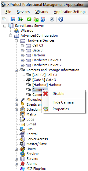
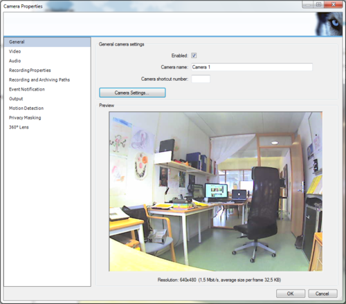
After adding the new camera(s) to the device list, they should appear in the tree structure under Cameras and Storage Information. Right click the IP Video Station camera and select Properties
If the image in the preview window is visible, no more actions are required.
If there is no image shown from the camera, click on the Camera Settings... button.
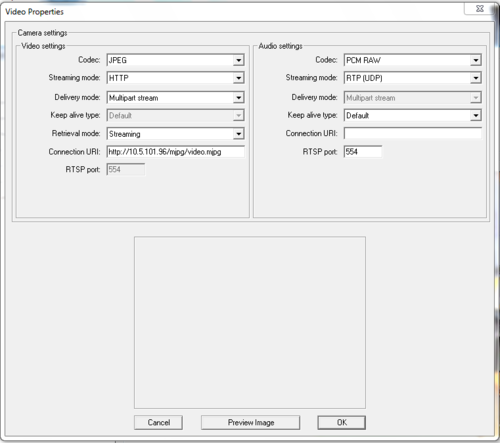
In the Video Properties set:
- 1 Codec: JPEG
- 2 Streaming mode: HTTP
- 3 Delivery mode: Multipart stream
- 4 Retrieval mode: Streaming
- 5 Connection URI: http://<camera IP address>/mjpg/video.mjpg
- 6 Click Preview Image to verify that the image is shown, followed by clicking OK.

