Difference between revisions of "IP Hotline Connections"
From Zenitel Wiki
(→INCA Based) |
(→Network Connection) |
||
| Line 26: | Line 26: | ||
See Related Article [[TKIS Connections]] for local power supply connections. | See Related Article [[TKIS Connections]] for local power supply connections. | ||
| − | |||
| − | |||
| − | |||
| − | |||
=== Input/Output Connections === | === Input/Output Connections === | ||
Revision as of 12:21, 23 June 2023
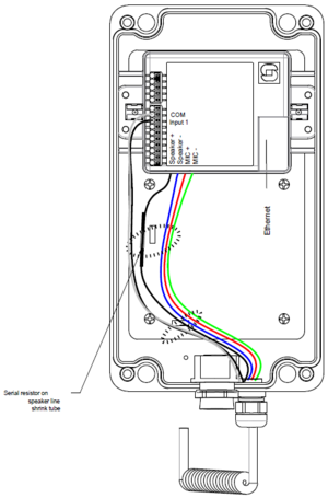
The IP Hotline comes with either the INCA IP Flush Master board, or the TKIS-2 kit inside.
Contents
Turbine Based
Introduction
The table below is an overview of the main connectors involved when installing the IP Hotline Station.
| Ethernet/Power | 10/100 Mbps Ethernet RJ-45 port for LAN (uplink) connection. Supports PoE (802.3af). Draws power from either spare line or signal line. |
| Secondary Power | 24 VDC (16 – 48 V) secondary power is provided from an external adapter. |
| Relays | There is one Double Throw relay contact with 60W switching power. COM, NO, NC contacts are provided. Max: 250VAC/220VDC, 2A, 60W |
| Input/Output | 6 general purpose I/Os are available. Each I/O can be configured as either input, output, or LED driver. |
| Audio Line Out | A balanced 600 ohm audio line out with induction loop signal |
To access these connectors the front cover must be removed.
Power Supply
The IP Hotline Station supports Power over Ethernet (PoE, IEEE 802.3 a-f) where power can be drawn from either the spare line or signal line.
If PoE is not available, the IP Hotline Station can be connected to a 24 VDC local power supply.
See Related Article TKIS Connections for local power supply connections.
Input/Output Connections
There are 6 I/O connection options for the IP Hotline Station. These connections can be used to interface with external I/O devices. The connections are typically used as digital input (eg. from a closing contact), digital output (5V), or LED driving (20mA max) for connecting sensors, indicators or integration to other systems.
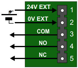
P2 - Relay Output and External Power Input
5-pin plug-on terminal for relay and external power
- Pin 1/2: 24 VDC for external secondary power if PoE is not used. Pin 1 is positive.
- Pin 3: COM relay (Common)
- Pin 4: NO relay (Normally Open)
- Pin 5: NC relay (Normally Closed)
- Relay switching capacity: Max. 60 watt (Max voltage: 250VAC/220VDC. Max current: 2A)
- Connectable conductors: 0.20 - 1.5 mm² (IEC) / 24 - 16 AWG (UL). Use of ferrules is recommended. Max cable size is then 0.75 mm².
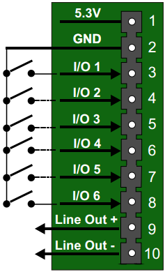
P3 - 10-pin plug-on terminal for I/O's and Audio Line Out
- Pin 1 5.3V (max. 200mA current)
- Pin 2 GND
- Pin 3 Input for Hookswitch for handset cradle (and for restoring Factory Default Setting)
- Pin 4 Button Input or LED Driver
- Pin 5 Button Input or LED Driver
- Pin 6 Button Input or LED Driver
- Pin 7 Button Input or LED Driver
- Pin 8 Button Input or LED Driver
- Pin 9 600 ohm balanced line out +
- Pin 10 600 ohm balanced line out -
- Connectable conductors: 0.20 - 1.5 mm² (IEC) / 24 - 16 AWG (UL). Use of ferrules is recommended. Max cable size is then 0.75 mm².
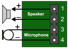
P4 - Loudspeaker & Electret microphone
- Pin 1: Speaker output +
- Pin 2: Speaker output -
- Pin 3: Electret Microphone +
- Pin 4: Electret Microphone -
- Connectable conductors: 0.20 - 1.5 mm² (IEC) / 24 - 16 AWG (UL). Use of ferrules is recommended. Max cable size is then 0.75 mm².
- Recommended loudspeaker impedance: 8 ohms

|
To enable the electret microphone input when using a TKIS-2, the "Product Model And Accessory" must be set to "Kit" under Station Main > Main Settings in the web interface of the device. |
For more details see Turbine Compact Board Connectors.


