AlphaCom XE7: Difference between revisions
From Zenitel Wiki
| Line 14: | Line 14: | ||
===<u>Connections</u>=== | ===<u>Connections</u>=== | ||
[[File:AC E7 Connection to AlphaCom E7.jpg|thumb|left|500px]] | |||
<br style="clear:both;" /> | |||
* The server is normally powered from the mains via a 24 VAC transformer. Battery backup power can be connected to the 24 VDC input plug. | |||
* Two RJ-45 Ethernet terminals are used for IP LAN, WAN, Internet and AlphaNet IP communication. Eth0 is also used for programming | |||
* All cables are terminated to connectors on the backplane. The two-pair star wired intercom cables and single-pair telephone cables are connected using pluggable screw connectors | * All cables are terminated to connectors on the backplane. The two-pair star wired intercom cables and single-pair telephone cables are connected using pluggable screw connectors | ||
* | * [[Physical number 5 and 6 (AlphaCom E7)|Connectors 5 and 6]] on the first ASLT line board are enabled for program distribution. Additional programs can be connected by substituting line boards with AGA boards with 6 programs per board | ||
* There are two inputs for clean contacts on the RCI connectors which can execute programmable functions. The 12 RCOs are connected to optional [[MRBD]] relay boards and can be programmed to execute functions such as door control | |||
* The serial ports with RS232 and RS422/RS485 interfaces are used for connecting to equipment using these protocols | * The serial ports with RS232 and RS422/RS485 interfaces are used for connecting to equipment using these protocols | ||
* | |||
* [[ | ====Serial Ports==== | ||
* | Serial Port 0 - 9-Pin D-sub (RS232 Only) | ||
[[File: | :No additional settings necessary | ||
---- | |||
Serial Port 1 - RJ45 (RS232/422/485) | |||
:Additional settings: | |||
:'''RS232:''' | |||
:* [[AMC-IP_-_AlphaCom_Processor_Board_(Red)#Switches_and_jumpers|Switch 8 on S601]] on the AMC-IP board must be set to OFF. | |||
:'''RS422:''' | |||
:* [[AMC-IP_-_AlphaCom_Processor_Board_(Red)#Switches_and_jumpers|Switch 8 on S601]] on the AMC-IP board must be set to ON. | |||
:* Set the two jumpers on the backplane in to the correct position. | |||
[[File:SerialPortJumpers XE7.png|thumb|left|500px|RS422/485 selector for Serial Port 1 on the XE7 backplane]] | |||
<br style="clear:both;" /> | <br style="clear:both;" /> | ||
Revision as of 13:55, 3 November 2016
Highlights
- Made to provide critical communication in any environment
- Supports 552 IP stations and 36 analog intercom stations
- SIM card based software configuration and disaster recovery
- Fully compatible with any AlphaCom system
Additional Documentation on Zenitel.com
Installation
Connections
- The server is normally powered from the mains via a 24 VAC transformer. Battery backup power can be connected to the 24 VDC input plug.
- Two RJ-45 Ethernet terminals are used for IP LAN, WAN, Internet and AlphaNet IP communication. Eth0 is also used for programming
- All cables are terminated to connectors on the backplane. The two-pair star wired intercom cables and single-pair telephone cables are connected using pluggable screw connectors
- Connectors 5 and 6 on the first ASLT line board are enabled for program distribution. Additional programs can be connected by substituting line boards with AGA boards with 6 programs per board
- There are two inputs for clean contacts on the RCI connectors which can execute programmable functions. The 12 RCOs are connected to optional MRBD relay boards and can be programmed to execute functions such as door control
- The serial ports with RS232 and RS422/RS485 interfaces are used for connecting to equipment using these protocols
Serial Ports
Serial Port 0 - 9-Pin D-sub (RS232 Only)
- No additional settings necessary
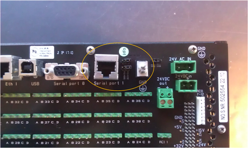
Serial Port 1 - RJ45 (RS232/422/485)
- Additional settings:
- RS232:
- Switch 8 on S601 on the AMC-IP board must be set to OFF.
- RS422:
- Switch 8 on S601 on the AMC-IP board must be set to ON.
- Set the two jumpers on the backplane in to the correct position.


