Difference between revisions of "ASLT - AlphaCom Subscriber Line Board"
From Zenitel Wiki
(→AlphaCom E20/E26) |
|||
| Line 1: | Line 1: | ||
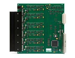
[[Image:910101 RS.jpg|thumb|250px|ASLT Subscriber Line Board]] | [[Image:910101 RS.jpg|thumb|250px|ASLT Subscriber Line Board]] | ||
| − | == | + | == Highlights == |
| − | * Can be used with InterGuard, TouchLine and Pamex [[stations]] | + | * Can be used with InterGuard, TouchLine and Pamex [[stations]] |
* Each board provides 6 subscriber connections | * Each board provides 6 subscriber connections | ||
* 6 [[RCO|RCO remote control outputs]] (software configurable activation) | * 6 [[RCO|RCO remote control outputs]] (software configurable activation) | ||
* 1 voice-switched conversation per board | * 1 voice-switched conversation per board | ||
| − | * When using handset or full duplex conference unit at both ends, the system is non-blocking within each module | + | * When using handset or full duplex conference unit at both ends, the system is non-blocking within each module |
* All subscriber connections suitable for display stations | * All subscriber connections suitable for display stations | ||
* Line monitoring | * Line monitoring | ||
| Line 13: | Line 13: | ||
* Red/green/amber LED indicates system status | * Red/green/amber LED indicates system status | ||
| − | == | + | ==Additional Documentation== |
| − | + | For more documentation please see http://www.zenitel.com/product/aslt | |
== Installation == | == Installation == | ||
| − | === AlphaCom | + | === AlphaCom XE20/XE26 === |
| − | |||
There are three different subscriber connection methods available: | There are three different subscriber connection methods available: | ||
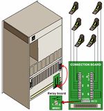
*Subscriber connection board ([[Subscriber Connection Board - 1009930200|1009930200]]) with 1.5 m connection cables ([[1009501011]]) or 3.0 m connection cable. | *Subscriber connection board ([[Subscriber Connection Board - 1009930200|1009930200]]) with 1.5 m connection cables ([[1009501011]]) or 3.0 m connection cable. | ||
| Line 25: | Line 24: | ||
*5 m ([[1009501021]]) and 10 m ([[1009501023]]) subscriber connection cables. These cables are un-terminated, [[Connection Cables - Color Code|color code]] is packed with the cables. | *5 m ([[1009501021]]) and 10 m ([[1009501023]]) subscriber connection cables. These cables are un-terminated, [[Connection Cables - Color Code|color code]] is packed with the cables. | ||
*Filter and connection card [[1009501041]] with RJ45 connectors. | *Filter and connection card [[1009501041]] with RJ45 connectors. | ||
| + | |||
| + | [[Image:Station and RCO connection to ASLT in E20 and E26.jpg|right|150px|thumb|Station and RCO connection to ASLT in AlphaCom XE20 and XE26]] | ||
<br style="clear:both;" /> | <br style="clear:both;" /> | ||
| − | === AlphaCom | + | === AlphaCom XE7 === |
| − | |||
All intercom stations are connected by means of pluggable screw terminals on the exchange back-plane. Line points 5 and 6 are by default used as program distribution inputs on line c-d when an ASLT board is placed in board pos. 1. | All intercom stations are connected by means of pluggable screw terminals on the exchange back-plane. Line points 5 and 6 are by default used as program distribution inputs on line c-d when an ASLT board is placed in board pos. 1. | ||
- The jumpers P5 and P6 are set to pos 2-3. | - The jumpers P5 and P6 are set to pos 2-3. | ||
| Line 38: | Line 38: | ||
- Reset the exchange | - Reset the exchange | ||
The RCO outputs 1-6 are associated with the board in pos. 1, and RCO 7-12 with the board in pos. 2. | The RCO outputs 1-6 are associated with the board in pos. 1, and RCO 7-12 with the board in pos. 2. | ||
| + | |||
| + | [[Image:Station, program and RCO connection to RCO in E7.jpg|150px|right|thumb|Station, program and RCO connection to ASLT in AlphaCom XE7]] | ||
| + | <br style="clear:both;" /> | ||
=== Cabling === | === Cabling === | ||
| Line 45: | Line 48: | ||
The four-wire interface provides compatibility with existing standard station range from STENTOFON with the exception of TouchLine display stations produced earlier than March 1995. These stations are no longer compatible due to reduction on the display signal output from the exchange. TouchLine display stations produced after March 1995 are labeled version 1.1 and are fully compatible with the AlphaCom exchange. | The four-wire interface provides compatibility with existing standard station range from STENTOFON with the exception of TouchLine display stations produced earlier than March 1995. These stations are no longer compatible due to reduction on the display signal output from the exchange. TouchLine display stations produced after March 1995 are labeled version 1.1 and are fully compatible with the AlphaCom exchange. | ||
| − | |||
| − | |||
| − | |||
| − | |||
| − | |||
| − | |||
| − | |||
| − | |||
| − | |||
| − | |||
| − | |||
| − | |||
| − | |||
| − | |||
| − | |||
| − | |||
| − | |||
| − | |||
| − | |||
| − | |||
| − | |||
| − | |||
| − | |||
| − | |||
| − | |||
| − | |||
| − | |||
| − | |||
| − | |||
| − | |||
| − | |||
| − | |||
| − | |||
| − | |||
| − | |||
| − | |||
| − | |||
| − | |||
[[Category:Hardware]] | [[Category:Hardware]] | ||
[[Category:Feature boards]] | [[Category:Feature boards]] | ||
Revision as of 09:00, 7 August 2015
Contents
Highlights
- Can be used with InterGuard, TouchLine and Pamex stations
- Each board provides 6 subscriber connections
- 6 RCO remote control outputs (software configurable activation)
- 1 voice-switched conversation per board
- When using handset or full duplex conference unit at both ends, the system is non-blocking within each module
- All subscriber connections suitable for display stations
- Line monitoring
- Software-controlled output volume control
- Hot plug-in/plug-out
- Red/green/amber LED indicates system status
Additional Documentation
For more documentation please see http://www.zenitel.com/product/aslt
Installation
AlphaCom XE20/XE26
There are three different subscriber connection methods available:
- Subscriber connection board (1009930200) with 1.5 m connection cables (1009501011) or 3.0 m connection cable.
- 2 pcs. of 1009930200 and 1009501011 are included with the E20 and E26 exchange packages.
- 5 m (1009501021) and 10 m (1009501023) subscriber connection cables. These cables are un-terminated, color code is packed with the cables.
- Filter and connection card 1009501041 with RJ45 connectors.
AlphaCom XE7
All intercom stations are connected by means of pluggable screw terminals on the exchange back-plane. Line points 5 and 6 are by default used as program distribution inputs on line c-d when an ASLT board is placed in board pos. 1. - The jumpers P5 and P6 are set to pos 2-3. - The potmeters P5 and P6 are used to adjust the input level. Line points 5 and 6 can also be used as normal subscriber points. - Set jumpers 5 and 6 to pos 1-2 - In AlphaPro, select Exchange & System >Boards - Change the port setting from ‘Audio program feed’ to ‘Default’ - Reset the exchange The RCO outputs 1-6 are associated with the board in pos. 1, and RCO 7-12 with the board in pos. 2.
Cabling
Desktop stations are connected to the line on RJ45 wall sockets.
Compatibility
The four-wire interface provides compatibility with existing standard station range from STENTOFON with the exception of TouchLine display stations produced earlier than March 1995. These stations are no longer compatible due to reduction on the display signal output from the exchange. TouchLine display stations produced after March 1995 are labeled version 1.1 and are fully compatible with the AlphaCom exchange.


