Configuration guide for IP Heavy Duty (SIP)
From Zenitel Wiki
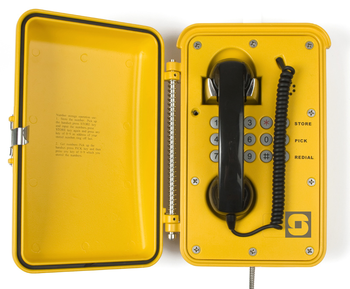
This article is applicable for IP Heavy Duty Stations used in Pulse mode and SIP mode. The configuration is done via the web interface of the station. For general configuration and setup of IP stations, see:
Set Station type
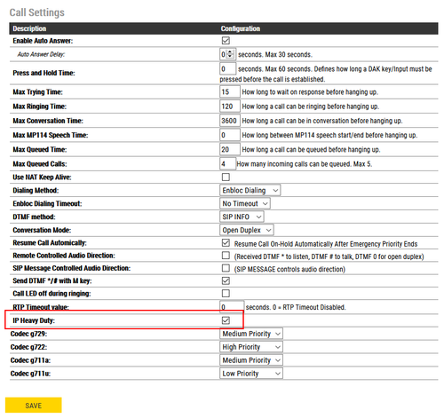
- In SIP Configuration -> Account/Call -> Call Settings, enable the "IP Heavy Duty" flag. This will ensure proper operation of handset and Direct Access keys (DAK).
The station must be rebooted for the setting to take effect.
Keyboard configuration
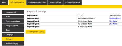
On the IP Heavy Duty station with full keypad, the keyboard configuration needs to be set.
- Select Advanced SIP > Keyboard, and set Keyboard Type = 3
Note that in Pulse mode the Keyboard configuration is not available in the web page. In order to set the "Keyboard Type", the station must temporarily be set to "SIP mode":
- In System Main > Main Settings, set Station Mode = Use SIP, then Save. There is no need to Apply.
- Select Advanced SIP > Keyboard, and set Keyboard Type = 3
- In System Main > Main Settings, set Station Mode = Use Pulse, then Save and Apply.
Hotline Call
When lifting the handset, input 3 of the station is triggered.
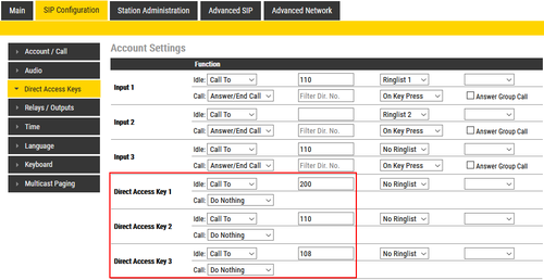
- Select SIP Configuration > Direct Access Key Settings, and enter the call destination on Input 3:
Direct Access Keys D1 to D3
The Full Keypad models have three Direct Access Keys, D1 to D3.
- To configure the DAK keys, select SIP Configuration > Direct Access Key Settings, and enter the call destinations on Direct Access Key 1 to 3:
Additional Call Indication
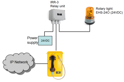
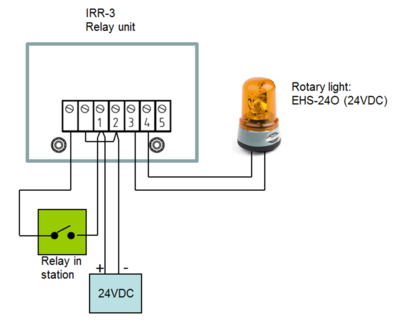
The built-in relay in the IP Heavy Duty station can be used to operate an additional call indication device, such as a rotary light.
Additional equipment required:
- Rotary light 24VDC (Item 300 6102 041)
- IRR-3 relay box (Item 102 0600 992)
- 24VDC power supply (Minimum 3A)
Connection diagram:
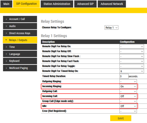
Configuration:
- To configure the relay, select SIP Configuration > Relay Settings, and select which events should turn the relay ON and OFF.
External loudspeaker (optional)
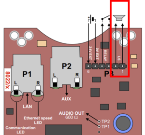
If ringing signal and group calls are to be received, an external 8 ohm loudspeaker must be connected. The loudspeaker is connected to pin 1 and 2 (LS) on connector P3. The external loudspeaker will be muted when the handset is lifted.
Note: The internal ringer device is not in use. The reason is that the housing of the IP telephones are also used in analog versions of the telephone, connected to regular 2-wire telephones lines. Then the ringer is operated by the ringing voltage from the telephone exchange. Although the ringer device is not in use in the IP Heavy Duty station, it has not been removed as it would jeopardize the IP rating of the station.

