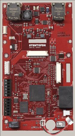
IP Master Station Kit - 1008093000
From Zenitel Wiki
Contents
Features
- Made for STENTOFON Critical Communication over IP (CCoIP)
- Supports full keyboard including direct access keys (DAK) and dynamic keys
- Supports handset and headset
- Superb audio quality
- 0dB (600 Ohm) output to Public Address
- Relay output for e.g. door lock control and tamper alarm input
- Dual Ethernet ports for connection of other IP devices
- Remote software upgrade, configuration and monitoring
Station Board Description
The IP Master Station Kit 100 8093 000 is delivered as a kit including board 8023, microphone and 2 x 6-pin plug-on screw terminals for local manufacturing of IP-CCoIP stations. The board is also used in STENTOFON standard IP flush mount master stations.
Connections
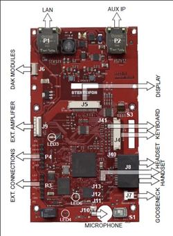
Station Board Connectors
| P1 | RJ45 LAN connector for 10/100 Mbit Ethernet connection. | ||
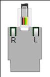
| The station can be powered from this connection if the line supports Power over Ethernet (PoE). The connector has two LEDs in front where the right (R) indicates Ethernet speed and the left (L) verifies Ethernet link and traffic. (L and R seen from the connector side). | |||
| P2 | RJ45 connector for auxiliary equipment like IP camera, PC or a second IP station. | ||
| This port has not an individual IP address. It does not carry power for AUX equipment. | |||
| P3 | 6-pin plug-on screw terminal for external connections. | ||
| Pin 1/2 | Connect to 1.5 W loudspeaker. Typical impedance: 8 Ω Recommended impedance: 6-25 Ω. | ||
| Pin 3/4 | Internal NO relay contact for door lock control etc. | ||
| Pin 5/6 | Connect 24 VDC for station power if PoE is not used. Pin 6 is positive. | ||
| P4 | 6-pin plug-on screw terminal for external connections. | ||
| Pin 1/4 | Input 1 | ||
| Pin 2/4 | Input 2 | ||
| Pin 3/4 | Input 3 | ||
| 5/6 | Station Led for vall message info. | ||
J4: 18-pin ZIF-connector for keyboard.
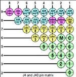
- The keyboard may have up to 10 dialling keys, M and C keys,10 DAK keys, 10 softkeys, volume up/down and light dim up/down keys connected in a matrix according to the drawing below.
J40: Optional keyboard connection.
J41: Optional DAK LED connection.
Connection to J40/41 can either be to a pin header or soldered directly to holes in the PCB.
- J4 and J40 pin1-9 Keyboard matrix
- J4/10 - J41/1 DAK1 Green LED
- J4/11 - J41/2 DAK1 Red LED
- J4/12 - J41/3 DAK2 Green LED
- J4/13 - J41/4 DAK2 Red LED
- J4/14 - J41/5 DAK3 Green LED
- J4/15 - J41/6 DAK3 Red LED
- J4/16 - J41/7 DAK4 Green LED
- J4/17 - J41/8 DAK4 Red LED
- J4/18 - J41/9 Common +3.3V
The DAK keys and the DAK LEDs are programmed using IND commands in the Event Handler. DAK1-4 and Soft-key 1-4 are used in current master stations.
Privacy on/off is accomplished by pressing “C” for 3 sec. A P is shown in the display during Privacy.
J5: 20-pin ZIF-connector for LCD display.
- Separate display panels are available as a kit of 5 units, 100 8099 000.
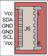
J6: 6-pin Wire-to-Board Connector for I2C-interface.
- Used for connection of DAK-modules.
- Pin 1: Vcc
- Pin 2: SDA (Data)
- Pin 3: GND
- Pin 4: GND
- Pin 5: SCL (Clock)
- Pin 6: Vcc
J7: 3-pin header for connecting gooseneck microphone.
- Pin 1: MIC+
- Pin 2: MIC-
- Pin 3: GND
J8: Dual RJ11 for handset and headset.
- Handset can optionally be connected via J11, J12 and J13.
Handset:
- Pin 1: Mic+
- Pin 2: Spk+
- Pin 3: Spk- (0 V)
- Pin 4: Mic-
- Pin 5: Hook-switch (must be connected to pin 3 with a switch)
- Pin 6: PTT (May not be supported by SW)
Headset:
- Pin 7: Mic+
- Pin 8: Spk+
- Pin 9: Spk-
- Pin 10: Mic-
- Pin 11: PTT Ground
- Pin 12: PTT (May not be supported by SW)
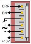
J9: 6-pin header for connecting external amplifier.
- 12 V/5 W can be supplied to the external amplifier.
- Signal to amplifier is balanced 0dBm 600 ohm.
- Pin 1: +13 V: max. 500 mA to amplifier
- Pin 2: LSN: negative line
- Pin 3: LSP: positive line
- Pin 4: GND
- Pin 5: AMP_EN enable signal to amplifier
- Pin 6: AMP_ERR error signal from amplifier
J10 Internal microphone.
- Pin 1: MIC+
- Pin 2: MIC-
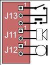
J11, 12 and 13 Pinheader for handset connection.
- Same as J8 pin 1 - 6.
- J11: Pin 1: Spk+
- J11: Pin 2: Spk-
- J12: Pin 1: Mic+
- J12: Pin 2: Mic-
- J13: Pin 1: OFFHOOK
- J13: Pin 2: GND
- J13: Pin 3: PTT
S1 Slide-switch to select internal mic. (Int) or gooseneck mic. (Ext).
S3 4-way DIP switch for future use.
- Leave all in default OFF position.
IP Station Configuration
IP intercom station web interface
An IP intercom station features an embedded web server, which allows users to log in via a standard web browser.
At commissioning, the IP station needs to be configured to make it possible for the IP station to register in an AlphaCom E Exchange.
Use the following procedure to connect to the IP station:
- Connect the LAN port P1 (Eth0) on the IP intercom station to the PC Ethernet port.
- Use a cross-over Ethernet cable if the PC Ethernet port does not cross, or connect both the PC and the IP intercom station to an Ethernet switch. Power the station with 24 VDC on P3 5/6 if PoE is not available.
- Open a web-browser and enter the IP address for the IP station in the address field.
- Default IP address: 169.254.1.100
- Click on Administrator login and enter:
User name (default: admin) and password (default: alphaadmin). (For software 01.06 and earlier the username is ADMIN and password is alphacom).
The Station Info page will now be visible, showing IP station configuration including the MAC-address of the station, which needs to be entered into AlphaPro exchange tool.
Use the menu bar at the top of each page to browse through the different pages.
CCoIP configuration
- Click on the menu item CCoIP configuration to access the web page used for configuration of IP parameters.
Registration Settings: Enter the AlphaCom E node IP address where the IP sta●●tion shall be a subscriber. CCoIP Station – IP Settings: DHCP ●●– Use this option if the IP station shall receive IP Settings from a DHCP server. Static IP ●●– Use this option if the IP station shall use a static IP address. Enter the IP-address, subnet mask and gateway address. Click ●●Save configuration followed by Apply to apply the new configuration settings.

