Audio Settings (Devices)
From Zenitel Wiki
 |
| Audio Settings - Advanced Configuration mode |
This article describes the Audio Settings for Zenitel IP devices running firmware version 7.1 or later. For description of older versions see Audio Settings (SIP) - older versions
From the Audio Settings page one can set loudspeaker volume, enable various audio signal processing feature and more.
Accessing the Audio Settings page
How to access the Audio Settings page depends on the mode of operation:
- Edge mode: Edge Configuration > Audio Settings
- SIP mode: SIP Configuration > Audio Settings
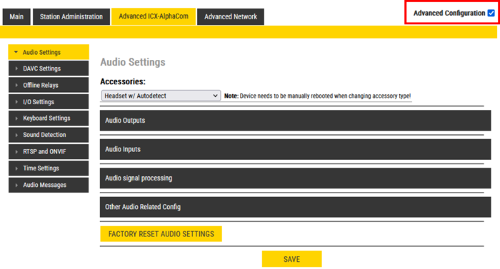
- ICX-AlphaCom mode: Advanced ICX-AlphaCom > Audio Settings

|
|
Normal Mode
"Normal mode" is the default view in the device web interface. One can set the level of the internal loudspeaker, as well as Line Out level and the output level on any accessories connected (e.g. handset, headset or external speaker).
In addition one can enable Automatic Gain Control (AGC), Active Noise Cancellation (ANC) and Automatic Volume Control (AVC). Not all these features are available for all types of devices.
- The available volume range for the loudspeaker depends on the intercom/device type. See this table for details.
- When the loudspeaker volume is set to 0dB (default) it will produce a nominal loudspeaker output of 65 dBA at 0.5 meter distance.
Devices in ICX-AlphaCom mode
When a device is used in ICX-AlphaCom mode the following settings are controlled by the ICX-AlphaCom server, and configured from AlphaPro:
- Internal Loudspeaker volume
- Automatic Noise Cancellation (ANC)
- Line Out level
These settings should not be changed in the device web interface, as they will be overwritten by the settings done from AlphaPro.
Advanced Configuration Mode
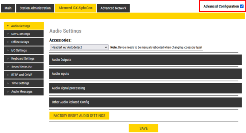
When selecting Advanced Configuration mode in the top right corner of the web interface, the Audio Settings page will change, and is divided into the following sections:
- Audio Outputs
- Audio Inputs
- Audio signal processing
- Other Audio Related Config (available in ICX-AlphaCom mode only)
Audio Outputs
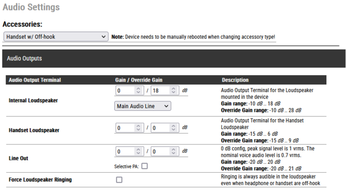
- Internal Loudspeaker: The value in the left field ("Gain") sets the regular volume. The value in the right field ("Override Gain") sets the volume when the Volume Override feature is active. For details, see here (Edge) and here (ICX-AlphaCom).
- On Turbine devices the "audio source" for playing in the speaker can be selected:
- Main Audio Line: Play audio from VoIP signal (default)
- Pure Line IN Signal: When the device is in idle play audio from the Line IN input. When the device is in a call, play audio from the VoIP signal
- Pure Line In+GPIO: When the device is in idle play audio from the Line IN input if Input 6 is active. When the device is in a call, play audio from the VoIP signal
- Handset Loudspeaker: Sets the level for regular volume (left filed) and Volume Override (right field). This setting appears only when Accessories = Handset (or Headset) is selected.
- Line Out: The value in the left field ("Gain") sets the regular volume. The value in the right field ("Override Gain") sets the volume when the Volume Override feature is active.
- Additional options available when "No Accessory" is selected:
- Main Audio Line: Play audio from VoIP signal
- Pure Mic Signal: Audio from microphone without any signal processing
- Processed Mic Signal: Audio from microphone with signal processing
- Selective PA: Used for special application. Leave it disabled.
- Force Loudspeaker Ringing: Enable the ringing signal from an incoming call to be heard in the internal loudspeaker if a headset, handset or external loudspeaker is used.
Stations with additional output for External Loudspeaker:
The IP Flush Master, IP-CROR and the TFIX-V2 series of stations have an additional output for external loudspeaker. This loudspeaker output needs to be enabled from the web interface, and volume can be configured separately from the internal speaker:
Audio Inputs
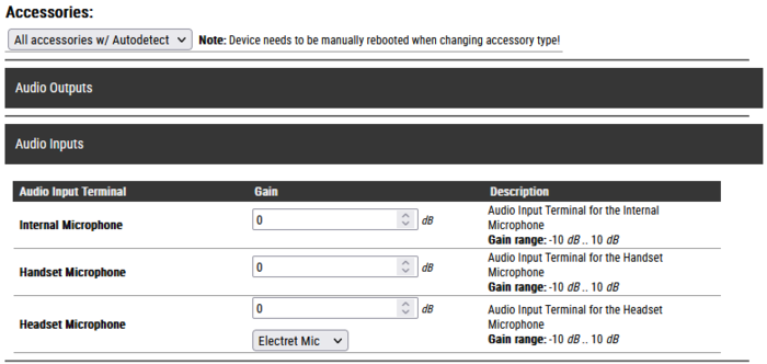
In this menu you select the input gain for the internal microphone, and other input sources that might be connected to the device.
If the device has headset or handset connected, the gain from this microphone can be adjusted separately:

On devices with Analog Line In option (e.g. TKIE kit), you can choose to use the microphone or the Line In as input source (only when "No Accessory" is selected):
On devices with a digital MEMS microphone (e.g. TCIS and TCIV+ stations), one can choose to use an external electret mic instead.
- Electret Mic: Use an electret microphone connected to the the analog mic input instead of the digital microphone.
- Digital Mic (default): Use the built-in MEMS microphone
There is also an option to switch between the internal digital mic and an external microphone by activating an input. This makes it possible to connect a handset or headset to TCIS/TCIV+, and connect the hook-switch of the handset to the input. One can choose which input to use for the hook-switch.
- I/O Pin A>D Switch: When the input is triggered, the analog mic input (e.g. handset) is enabled. When the input is not triggered, the digital mic is enabled. The input must be configured as "Input" in the IO Settings page.
- I/O Pin A>D Switch (until call-end): When the input is triggered, the analog mic input (e.g. handset) is enabled. When the call is ended the digital mic is enabled.
Audio signal processing
From the Audio signal processing menu you can configure a number of audio related features. Below are links that describes each feature, and how it is configured:
- Automatic Gain Control (AGC)
- Acoustic Echo Cancellation (AEC)
- Active Noise Cancellation (ANC)
- Far End Signal Squelch (FESS)
- Dynamic Range Compression (DRC)
- Automatic Volume Control (AVC)
Other Audio Related Config
New default settings
IP Intercom
The IP-station audio output has been normalized based on ITU recommendations. The input signal which is used for the output measurements is an ITU Voice Signal with an average RMS energy of -23 dBFS. Output levels are measured at a distance of 0.5 meter. The actual SPL of the IP-CROR station is 3 dB lower than indicated in the table below due to the covering of the speaker grill with a foil.
Kit output levels are based on the same speaker arrangement as for the comparable station.
| Product family | Gain range | |||
| Minimum | Default | Maximum | Override maximum | |
| TCIS/TICV/TCIV+/TKIV+/TKIS | -10 | 0 | +13 | +23 |
| TFIE/TKIE | -10 | 0 | +18 | +28 |
| TMIS/TMIV+ | -17 | 0 | +4 | +14 |
| ECPIR | -17 | 0 | +4 | +14 |
| TFIX | -10 | 0 | +3 | +4 |
| TFIX-V2 | -10 | 0 | +3 | +4 |
| IP Desk Master (100840xxxx) | -8 | 0 | +16 | +18 |
| IP Flush Master (1008431000) | -14 | 0 | +10 | +12 |
| IP-Station, Clean Room/OR (1008415000) | -14 | 0 | +10 | +12 |
IP Speakers
The IP Speaker audio output has been normalized based on ITU recommendations. The input signal which is used for the output measurements is an ITU Voice Signal with an average RMS energy of -23 dBFS. Output levels are measured at a distance of 1.0 meter
| Product family | Gain range | |||
| Minimum | Default | Maximum | Override maximum | |
| ELSII-10WM | -10 | 10 | +16 | +17 |
| ELSIR-10CM | -10 | 10 | +16 | +17 |
| ELSII-10HM | 0 | 10 | +29 | +30 |
| ELSII-10LHM | 0 | 10 | +35 | +36 |
| ELSII-10PM | -10 | 10 | +13 | +14 |


