External Communication configuration guide
From Zenitel Wiki

This article describes how to set up AlphaCom, Cisco Call Manager 6, Mediant 1000 and MP-114 for application External Communication.
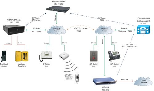
Components used in this example:
- AlphaCom XE7 (AMC Board Version 11.1.9.1)
- Cisco Unified Call Manager (System Version 6.1.2.1000-13)
- Mediant 1000 (Firmware Version 6)
- MP-114 (Firmware Version 5.4)
- AlphaCom Stations (Traditional Intercom, Analogue Telephone, IP Station, SIP Station)
- Cisco SIP Station 7961
AlphaCom XE7 Configuration
AlphaWeb XE Configuration
Assign IP address to the AlphaCom XE7 Ethernet Port(s)
Log on to AlphaWeb and enter a valid IP address on the Ethernet port(s).
In the example below, Eth.0 has a default configuration and Eth.1 is used for AlphaNet.
Consult your network administrator to obtain the IP address.

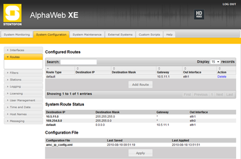
Assign IP routing to the AlphaCom XE7 Ethernet Port(s)
Log on to AlphaWeb and create a default routing for the port used for AlphaNet.
In the example below, Eth.1 is used for AlphaNet.
This is essential because the ACE and the CUCM are on two different networks.
Insert license key to the AlphaCom XE7
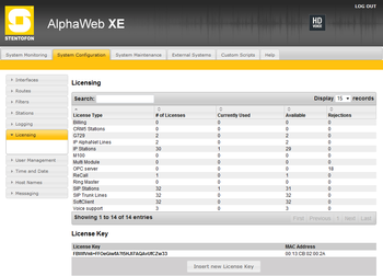
Log on to AlphaWeb and install the License Key.
In the example below, it is necessary to use a license with IP AlphaNet Lines, SIP Trunk Line, IP Stations, SIP Stations.
Firewall Filter Settings to the AlphaCom XE7
Log on to AlphaWeb and Active/Desactive the filters in function of your application.
In the example below, all filters are active.

AlphaPro Configuration
Create a SIP Trunk(s) Node(s)
For the External Communication application it's necessary create two SIP Trunks Nodes, the first for exchange with the Mediant1000 and the second for register CUCM.
From the AlphaPro main menu :
1: Use the "+" button next to the "Select Exchange" dropdown list to create a new exchange.
2: The exchange type must be set to "SIP Node".
3: Set the parameters as shown in the figures below.


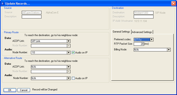
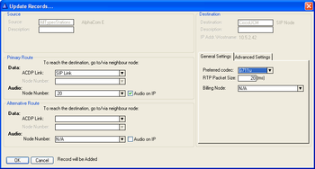
Define the AlphaNet Routing
In "Exchange & System" and "Net Routing" use the "Insert" button to create a route :
First between the AlphaCom and the Mediant 1000,
Second between AlphaCom and Cisco Unified Call Manager.
Set the parameters as shown in the figures below.
Create Access Numbers
The Cisco phones can be accessed in three different ways:
- Prefix number: Dial Prefix + Phone number. “Phone number” will be called
- Integrated Prefix number: Dial Prefix + Phone number. The prefix will be included as a part of the called telephone number
- Global number: Dial the phone number without using prefix
Prefix number
The directory number must be programmed in the AlphaCom directory table with feature 81 and Node = SIP Trunk node number (10 in this example).
In the field “Parameter 2” you must enter the maximum number of digits in a phone number.
When the prefix is dialed, the AlphaCom will wait for more digits. When the number of digits specified in the “Parameter 2” is collected, a call setup message is sent to the Cisco Unified Call Manager by Mediant 1000.
If fewer digits are entered, the AlphaCom will time out after 4 seconds, and the call setup message will be sent.
You can also terminate the digit collection by pressing the M-key. The call setup message will then be sent immediately.
In the example below the directory number 0 is used as a prefix.
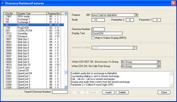
Dialing examples:
- 0 + 1234: Telephone number 1234 will be called
- 0 + 123: After a 4 second timeout, telephone number 123 will be called
- 0 + 123 + M: Telephone number 123 will be called
Integrated Prefix number
The directory number must be programmed in the AlphaCom directory table with feature 83 and Node = SIP Trunk node number (10 in this example).
In the field “Parameter 2” you must enter the maximum number of digits in a phone number.
When the prefix is dialed, the AlphaCom will wait for further digits. When the number of digits specified in the “Parameter 2” is collected, a call setup message is sent to the Cisco Call Manager by Mediant 1000.
If fewer digits are entered, the AlphaCom will time out after 4 seconds, and the call setup message will be sent.
You can also terminate the digit collection by pressing the M-key. The call setup message will then be sent immediately.
In the example below the directory number 57 is used as a prefix.
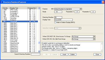
Dialing examples:
- 50 + 1234: Telephone number 501234 will be called
- 50 + 123: After a 4 second timeout, telephone number 50123 will be called
- 50 + 123 + M: Telephone number 50123 will be called
Global number
The directory number must be programmed in the AlphaCom directory table with feature 83 and Node = SIP Trunk node number (10 in this example).
The field “Parameter 2” must be left blank.
When the global number is dialed, the AlphaCom will immediately send a call setup message to the Cisco Call Manager by Mediant 1000.
In the example below the directory number 3512 is defined as a global number.
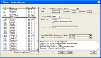
When dialing this number a call setup message is sent to the Cisco Call Manager by Mediant 1000, instructing it to call this phone number.
Update the exchange
Log on to the exchange and update the exchange by pressing the SendAll button. Reset the exchange when the transfer is finnished.
Cisco Unified Call Manager Configuration
- Open a browser window and type in the IP address of your Cisco Unified Call Manager (CUCM)
- Log on to Cisco Unified CM Administration
- Execute the following configuration: (Parameters not mentioned should be left untouched to their default setting)
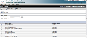
Service Activation
Navigation -> Cisco Unified Serviceability
- Tools -> Service Activation
- Activate the following services:
- Cisco CallManager
- Cisco Tftp
- Cisco IP Voice Media Streaming App
- Press Save (takes some time)
Global configuration
Date/Time Group
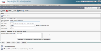
- System -> Date/Time Group -> Add New
- Group Name: Zenitel
- Time Zone: Choose your time zone
- Separator: -(dash)
- Date Format: Choose your date format
- Time Format: Choose your time format
- Phone NTP References: Add a Phone NTP References if your network is equiped
- Press Save
- Press Reset/Restart
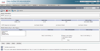
Region
For External Communication application it's necessary create two "Region", for that the phones used with CUCM supports the two codecs (G711 and G729).
First
- Add New
- Name: Codec_G729
- Press Save
Second
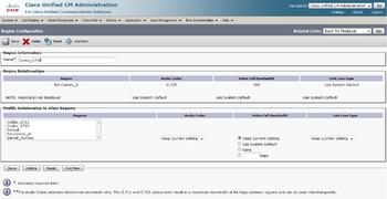
- Add New
- Name: Ext.Comm._R
- Modify Relationship: Select Regions "Codec_G729" -> Audio Codec "G729" -> "Keep Current Setting" for other parameters
- Press Save
- Press Reset/Restart
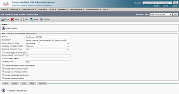
SIP Trunk Security Profile
- System -> Security Profile -> SIP Trunk Security Profile -> Add New
- Name: Ext.Comm._SIPTSPI
- Description: Zenitel External Communication SIP Secure Profile
- Device Security Mode: Non Secure
- Incoming Transport Type: TCP+UDP
- Outgoing Transport Type: UDP
- Enable:
- Accept Presence Subscription
- Accept Out-of-Dialog REFER
- Accept Unsolicited Notification
- Accept Replaces Header
- Press Save
- Press Reset/Restart
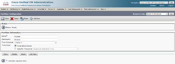
Partition
- Call Routing -> Class of Control -> Partition -> Add New
- Name: AllLines
- Press Save
- Press Reset/Restart
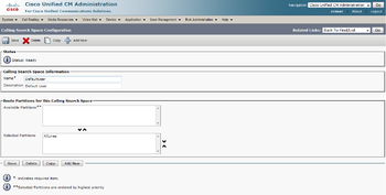
Calling Search Space
- Call Routing -> Class of Control -> Calling Search Space -> Add New
- Name: DefaultUser
- Description: DefaultUser
- Select AllLines in the ”Available Partitions” window and use the ”Move Down” arrow to move it to the ”Selected Partitions” window.
- Press Save
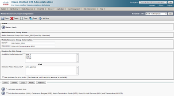
Media Resource Group
- Media Resources -> Media Resource Group -> Add New
- Name: Ext.Comm._MRG
- Description: Eternal Communication MRG
- Select MTP_2 in the ”Available Media Resources” window and use the ”Move Down” arrow to move it to the ”Selected Media Resources” window.
- Press Save
- Press Reset/Restart
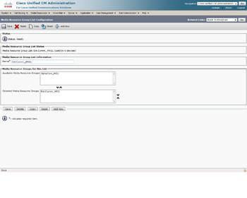
Media Resource Group List
- Media Resources -> Media Resource Group List -> Add New
- Name: Ext.Comm._MRGL
- Select Ext.Comm._MRG in the ”Available Media Resource Groups” window and use the ”Move Down” arrow to move it to the ”Selected Media Resource Groups” window.
- Press Save
- Press Reset/Restart
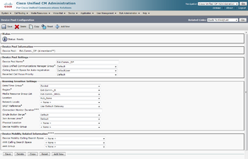
Device Pool
- System -> Device Pool -> Add New
- Name: Ext.Comm._DP
- Cisco Unified Communications Manager Group: Default
- Calling Search Space for Auto-registration: DefaultUser
- Reverted Call Focus Priority: Default
- Date/Time Group: Zenitel
- Region: Ext.Comm._R
- Media Resource Group: Ext.Comm._MRGL
- Location: Hub_None
- SRST Reference: Use Default Gateway
- Press Save
- Press Reset/Restart
Configuration exchange between CUCM and Mediant1000
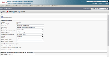
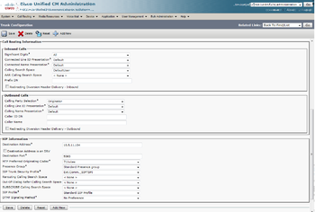
Trunk
- Device -> Trunk -> Add New
- Trunk Type: SIP Trunk
- Device Protocol: SIP
- Press Next
- Device Name: Ext.Comm._Mediant1000
- Description: External Communication Mediant1000
- Device Pool: Ext.Comm._DP
- Media Resource Group List: Ext.Comm._MRGL
- Enable: 'Media Termination Point Required'
- Calling Search Space: DefaultUser
- Destination Adress: IP adress Mediant1000
- SIP Trunk Security Profile: Ext.Comm._SIPTSPI
- SIP Profile: Standard SIP Profile
- Press Save
- Press Reset/Restart
Route Group
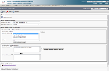
- Call Routing -> Route/Hunt -> Route Group -> Add New
- Name: Ext.Comm._Mediant1000_RG
- Select Ext.Comm._Mediant1000 from ”Available Devices” and press ”Add to Route Group”
- Press Save
Route List
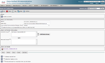
- Call Routing -> Route/Hunt -> Route List -> Add New
- Name: Ext.Comm._Mediant1000_RL
- Description: External Communication Mediant1000 Route List
- Cisco Unified Communications Manager Group: Default
- Press Save
- Press Add Route Group
- Route Group: Ext.Comm._Mediant1000_RG-[NON-QSIG]
- Press Save
- Press Save
- Press Reset/Restart
Route Pattern
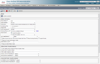
- Call Routing -> Route/Hunt -> Route Pattern -> Add New
- Route Pattern: 1xx (This allows calls to all numbers beginning with 1 and with 3digits in the AlphaCom)
- Route Partition: AllLines
- Description: External Communication Mediant1000 RP Wiring Phone
- Gateway/Route List: Ext.Comm._Mediant1000_RL
- Press Save

Configuration exchange between CUCM and MP-114
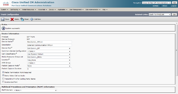
Trunk
- Device -> Trunk -> Add New
- Trunk Type: SIP Trunk
- Device Protocol: SIP
- Press Next
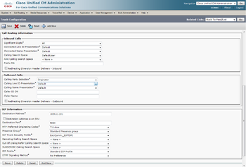
- Device Name: Ext.Comm._MP114
- Description: External Communication MP114
- Device Pool: Ext.Comm._DP
- Media Resource Group List: Ext.Comm._MRGL
- Enable: 'Media Termination Point Required'
- Calling Search Space: DefaultUser
- Destination Adress: IP adress MP114
- SIP Trunk Security Profile: Ext.Comm._SIPTSPI
- SIP Profile: Standard SIP Profile
- Press Save
- Press Reset/Restart
Route Group
- Call Routing -> Route/Hunt -> Route Group -> Add New
- Name: Ext.Comm._MP114_RG
- Select Ext.Comm._MP114 from ”Available Devices” and press ”Add to Route Group”
- Press Save

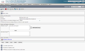
Route List
- Call Routing -> Route/Hunt -> Route List -> Add New
- Name: Ext.Comm._MP114_RL
- Description: External Communication MP114 Route List
- Cisco Unified Communications Manager Group: Default
- Press Save
- Press Add Route Group
- Route Group: Ext.Comm._MP114_RG-[NON-QSIG]
- Press Save
- Press Save
- Press Reset/Restart
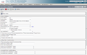
Route Pattern
- Call Routing -> Route/Hunt -> Route Pattern -> Add New
- Route Pattern: 001 (Allows the access to the PSTN Network connected to MP-114)
- Route Partition: AllLines
- Description: External Communication MP114 RP PSTN Network
- Gateway/Route List: Ext.Comm._MP114_RL
- Press Save

Cisco SIP Station 7961
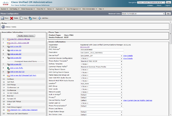
Phone
- Device -> Phone -> Add New
- Phone Type: Choose your SIP station type from the drop down list
- Press Next
- Select the device protocol: SCCP (This is the standard Cisco SIP station protocol).
- Press Next
- MAC Address: Enter your SIP station MAC address
- Description: Ext.Comm._3512_Secretary
- Device Pool: Ext.Comm._DP
- Phone button Template: Choose your SIP station specific template
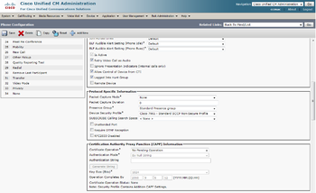
- Device security Profile: Choose your SIP station specific profile
- Press Save


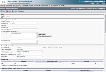
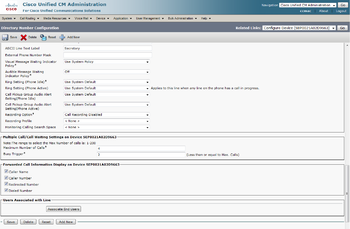
- In the upper left corner press ”Line [1] – Add a new DN]
- Enter wanted directory number (here 3512)
- Route Partition: AllLines
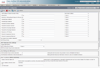
- Calling Search Space: defaultUser
- ASCII Display (Internal Caller ID): Secretary (This is the wanted name for the phone. This name will be displayed in the AlphaCom stations, and should thus be configured the same as the Global Number in the AlphaCom)
- Line Text Label : Secretary
- ASCII Line Text Label : Secretary
- Press Save
- Press Reset/Restart
Zenitel SIP Station
Software requirement: The Zenitel SIP station must have firmware 01.11.x.x or later
Phone
- Device -> Phone -> Add New
- Phone Type: Third-party SIP Device (Basic)
- Press Next
- MAC Address: Enter your Zenitel SIP Station MAC address
- Description: Ext.Comm._1155_Entrance
- Device Pool: Ext.Comm._DP
- Phone button Template: Third-party SIP Device (Basic)
- Calling Search Space: DefaultUser
- Media Resource Group List: Ext.Comm._MRGL
- Device Security Profile: Third-party SIP Device (Basic) - Standard SIP - Non-secure
- SIP Profile: Standard SIP Profile
- Press Save

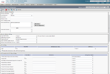
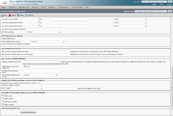
- In the upper left corner press ”Line [1] – Add a new DN]
- Enter wanted directory number (here 1155)
- Route Partition: AllLines
- Calling Search Space: DefaultUser
- ASCII Display (Internal Caller ID): Entrance
- Press Save
- Press Reset/Restart
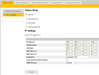
Log on to your Zenitel SIP Station by entering the IP address of the station in your web browser.
CCoIP Station Settings
- Station Main -> Main Settings
- CCoIP Station Mode: Use SIP
- CCoIP Station - IP Settings: DHCP
- Press Save configuration
- Press Reboot, and OK.
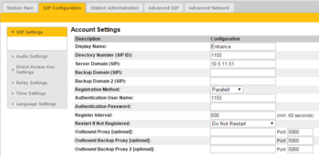
SIP Account Settings
- SIP Configuration -> SIP Settings
- SIP Display Name: Entrance
- SIP ID: 1155
- SIP Domain: Your CUCM IP Address
- Authenitcaion User Name: 1155
- Press Save SIP configuration
- Press Reboot, and OK.
Call Button Settings
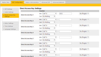
- SIP Configuration -> Direct Access Key Settings
- Here you define the call pattern of your SIP Intercom.
Mediant1000 Configuration
For the application External Communication the Mediant1000 is used for his SIP2SIP routing and Transcoding capability.
The basic configuration is :
- 1 x Mediant 1000 chassis for voice module (M1K-CH)
- 1 x Media Processing Module (M1K-VM-MPM) or 1 x Digital Trunks Module (?)
- The configuration with MPM card is cheaper that with DTM card
- 1 x License SIP to SIP Mediation and Routing Application (SW/IP2IP/10)
With this configuration, the Mediant1000 active 20 Media Channels that can support 10 transcoding simultane session.
To increase the sessions capability different configurations. The Mediant1000 support 3 MPM card or 4 DTM card and 1 License is for 10 transcoding session.
- 1 Module = 20 Media Channels (10 transcoding sessions = 1 License)
- 2 Modules = 60 Media Channels (30 transcoding sessions = 3 Licenses)
- 3 Modules = 100 Media Channels (50 transcoding sessions = 5 Licenses)
- 4 Modules = 120 Media Channels (60 transcoding sessions = 6 Licenses)
Restore to factory default settings
- With a paper clip, press and hold down the Reset button (located on the CPU Module) for at least 12 seconds (no more than 25 seconds)
- The device restores to factory default settings
- With a paper clip, press and hold down the Reset button (located on the CPU Module) for at least 12 seconds (no more than 25 seconds)

Access to the embedded web server
The default Network parameter of the Mediant 1000:
- IP Adress : 192.168.0.2
- Subnet Mask : 255.255.255.0
- Default Gateway : 192.168.0.1
Connect your PC directly to the device, using an Ethernet Crossover cable
Before the PC can access to the Mediant1000, the IP address of the PC must be changed to match the same subnet (e.g 192.168.0.11)
To access the embedded web server, start your internet browser (e.g. Internet Explorer) and in the address field enter 192.168.0.2.
You will be prompted for a username and password (default):
- Username: Admin
- Password: Admin
The Home Page page should now be displayed
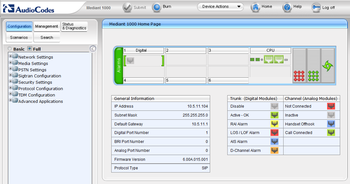
Note: For the rest of configuration used the tree menu in Full mode
IP Configuration
In the "IP Settings" page (Configuration tab -> Network Settings menu -> IP Settings page) enter:
- IP Adress
- Subnet Mask
- Default Gateway
- Click "Submit" to apply the changes

The IP address is immediately changed when pressing Submit, but it is not permanently stored
Without resetting or powering off the device, you need to log on to the Gateway using its new IP address in order to Burn the new IP address to flash:
- Disconnect the PC from the Gateway
- Connect the Gateway and PC to the LAN. The PC and Gateway must be on the same sub-net
- Restore the PC’s IP address and subnet mask to what they originally were, and re-access the Gateway using the new assigned IP address
- Click "Burn" to permanently apply the changes
Enable IP-to-IP Capabilities
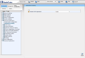
In the "Applications Enabling" page (Configuration tab -> Protocol Configuration menu -> Applications Enabling page):
- From the "Enable IP2IP Application" drop-down list, select "Enable"
- Submit & Burn
- Wait the next step for Reset the device
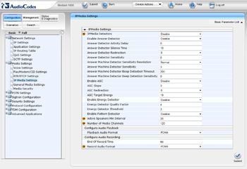
Number of Media Channels
In the "IP Media Settings" page (Configuration tab -> Media Settings menu -> IP Media Settings page):
- In the "Number of Media Channeles" field, enter the required number of media channels (directly enter "120", maximum capacity of Mediant1000)
- Submit & Burn
- Reset the device (Device Action -> Reset -> Reset)
Proxy Sets Table
These "Proxy Sets" are later assigned to "IP Groups". Note that the "Proxy Set" represents the actual destination to which the call is routed.
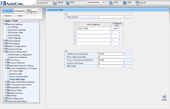
In the "Proxy Sets Table" page (Configuration tab -> Protocol Configuration menu -> Proxies,Registration,IP Groups submenu -> Proxy Sets Table page):
- Proxy Set ID#1 for AlpahCom XE7
- From the "Proxy Set ID" drop-down list, select "1"
- In the "Proxy Address" column, enter the IP address of the AlphaCom
- From the "Transport Type" drop-down list corresponding to the IP address entered above, select "UDP"
- Submit
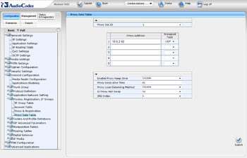
- Proxy Set ID#2 for CiscoUCM
- From the "Proxy Set ID" drop-down list, select "2"
- In the "Proxy Address" column, enter the IP address of the CUCM
- From the "Transport Type" drop-down list corresponding to the IP address entered above, select "UDP"
- Submit & Burn
IP Group Table
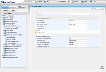
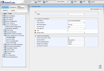
These "IP Groups" are later used by the device for routing calls In the "IP Group Table" page (Configuration tab -> Protocol Configuration menu -> Proxies,Registration,IP Groups submenu -> IP Group Table page):
- IP Group #1 for AlpahCom XE7
- From the "Index" drop-down list, select "1"
- In the "Description" field, type an arbitrary name for the IP Group (e.g. AlphaCom)
- From the "Proxy Set ID" drop-down list, select "1" (For this "IP Group" communicate with the "Proxy Set" of the AlphaCom)
- In the "SIP Group Name" field, enter the IP Adress sent in the SIP Request From/To headers for this IP Group (AlphaCom's IP Adress)
- Contact User = name that is sent in the SIP Request contact header for this IP Group (e.g. acm)
- Submit
- IP Group #2 for CUCM
- From the "Index" drop-down list, select "2"
- In the "Description" field, type an arbitrary name for the IP Group (e.g. CiscoUnifiedCallManager)
- From the "Proxy Set ID" drop-down list, select "2" (For this "IP Group" communicate with the "Proxy Set" of the CUCM)
- In the "SIP Group Name" field, enter the IP Adress sent in the SIP Request From/To headers for this IP Group (CUCM's IP Adress)
- Contact User = name that is sent in the SIP Request contact header for this IP Group (e.g. cucm)
- Submit & Burn
IP Profiles for Voice Coders
For use transcoding it's necessary create two IP Profiles for define two types of coders used.
These profiles are later used in the "Inbound IP Routing" and "Outbound IP Routing" tables.
In the "Coder Group Settings" page (Configuration tab -> Protocol Configuration menu -> Coders And Profile Definitions submenu -> Coder Group Settings page):
- Coder Group ID#1 for AlpahCom XE7
- From the "Coder Group ID" drop-down list, select "1"
- In the "Coder Name" drop-down list, select "G.711U-law" (Coder used by AlphaCom)
- Submit

- Coder Group ID#2 for CUCM
- From the "Coder Group ID" drop-down list, select "2"
- In the "Coder Name" drop-down list, select "G.729" (Coder used by CUCM)
- Submit & Burn

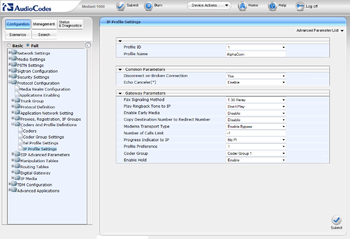
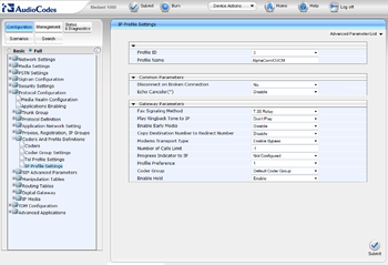
In the "IP Profile Settings" page (Configuration tab -> Protocol Configuration menu -> Coders And Profile Definitions submenu -> IP Profile Settings page):
- Profile ID#1 for AlpahCom XE7
- From the "Profile ID" drop-down list, select "1"
- From the "Coder Group" drop-down list, select "Coder Group 1"
- Submit
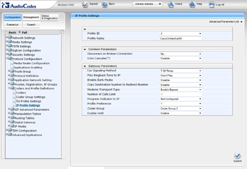
- Profile ID#2 for CUCM
- From the "Profile ID" drop-down list, select "2"
- In the "Coder Group" drop-down list, select "Coder Group 2"
- Submit & Burn
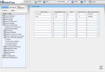
OR it's possible to use "Default Coder Group" with both coders (G711U-law and G729) and use it in a common "IP Profile"
- (the above solution is preferred for differentiate AlphaCom and CUCM throughout configuration)
Inbound IP Routing
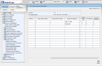
The "IP to Trunk Group Routing Table" it used for define the routing inbound IP-to-IP calls.
The table in which this is configured uses the IP Groups that you defined before.
In the "IP to Trunk Group Routing Table" page (Configuration tab -> Protocol Configuration menu -> Routing Tables submenu -> IP to Trunk Group Routing page):
- Index#1 for AlpahCom XE7
- Dest Phone Prefix : enter the asterisk (*) symbol to indicate all destinations
- Source Phone Prefix : enter the asterisk (*) symbol to indicate all destinations
- Source IP Adress : enter the IP adress of the AlphaCom
- Trunk Group ID : enter "-1" to indicate that these calls are IP-to-IP calls
- IP Profile ID : enter "1" to assign these calls to "ProfileID#1" to use "G.711U-law"
- Source IP Groupe ID : enter "1" to assign these calls to the IP Group pertaining to the AlphaCom
- Index#2 for CUCM
- Dest Phone Prefix : enter the asterisk (*) symbol to indicate all destinations
- Source Phone Prefix : enter the asterisk (*) symbol to indicate all destinations
- Source IP Adress : enter the IP adress of the CUCM
- Trunk Group ID : enter "-1" to indicate that these calls are IP-to-IP calls
- IP Profile ID : enter "2" to assign these calls to "ProfileID#2" to use "G.729"
- Source IP Groupe ID : enter "2" to assign these calls to the IP Group pertaining to the CUCM
- Submit & Burn
Outbound IP Routing
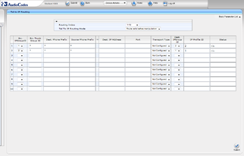
The "Tel to IP Routing Table" it used for define the routing outbound IP-to-IP calls.
The table in which this is configured uses the IP Groups that you defined before.
In the "Tel to IP Routing" page (Configuration tab -> Protocol Configuration menu -> Routing Tables submenu -> Tel to IP Routing page):
- Index#1 from AlpahCom XE7 to CUCM
- Src.IPGroupID : select "1" to indicate received (inbound) calls identified as belonging to the IP Group configured for AlphaCom
- Dest. Phone Prefix : enter the asterisk (*) symbol to indicate all destinations and callers respectively
- Dest.IPGroupID : select "2" to indicate the destination IP Group to where these calls are sent, to the CUCM.
- IP Profile ID : enter "2" to indicate the IP Profile configured for "G.729" (If you use the "Default Coder Group", select the number of your common "IP Profile")
- Index#2 from CUCM to AlphaCom XE7
- Src.IPGroupID : select "2" to indicate received (inbound) calls identified as belonging to the IP Group configured for CUCM
- Dest. Phone Prefix : enter the asterisk (*) symbol to indicate all destinations and callers respectively
- Dest.IPGroupID : select "1" to indicate the destination IP Group to where these calls are sent, to the AlphaCom.
- IP Profile ID : enter "1" to indicate the IP Profile configured for "G.711U-law" (If you use the "Default Coder Group", select the number of your common "IP Profile")
- Submit & Burn
