ENA Amplifier Configuration (SIP)
From Zenitel Wiki
This article describes the configuration settings available via the web interface of the ENA IP Network Amplifier in SIP mode.
Functions available in advanced configuration mode can be found here.
Main
Information
- Log In to the amplifier
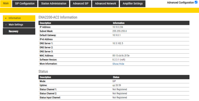
- The Information page will now be displayed, showing the amplifier configuration and status.

|
|
Main Settings
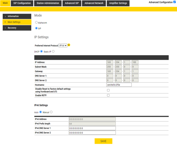
- Click Station Main > Main Settings to access the page for configuring Station Mode and IP parameters.
Mode: Select the SIP radio-button.
Preferred Internet Protocol: Select either IPV4 or IPV6. (Not available in the ENA2060 amplifier).
IP Settings:
- DHCP – Select this option if the IP station shall receive IP Settings from a DHCP server.
- Static IP – Select this option if the IP station shall use a static IP address. Enter values for:
- - IP-address
- - Subnet-mask
- - Gateway
- - DNS Server 1 (option for network administration)
- - DNS Server 2 (option for network administration)
- - Hostname (option for network administration)
- Disable Reset to Factory default settings using frontboard and I/O: If enabled, factory reset will only be possible from the web interface. This is disabled by default.
- Enable RSTP: RSTP is only required when using redundant networking (Not available in the ENA2060 amplifier).
Click Save followed by Apply to apply the new configuration settings.
Time Settings (Available in the ENA2060 amplifier only).
- Enable Network Time Protocol, set the IP address of the NTP Server, Select Region and Zone
Recovery
- Full reboot: Perform a full Linux reboot. No configuration is lost
- Partial reboot: Perform a restart of the intercom application. No configuration is lost
- Factory reset: Set all parameters to Factory Default values. The amplifier will get static IP Address 169.254.1.100.
- Factory reset with DHCP: Set all parameters to Factory Default values. The amplifier will get IP Address from DHCP server. If no DHCP server in the network, it will get a random 169.254.x.x IP address.
SIP Configuration
Account/Call
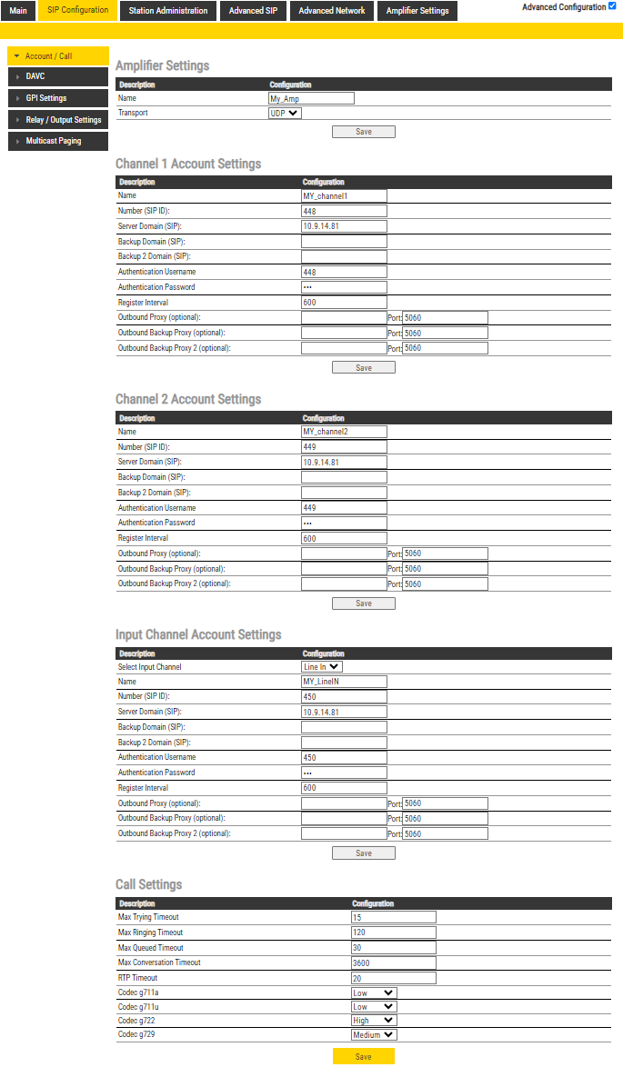
Select SIP Configuration -> Account/Call to access the page for configuring the SIP Account Settings.
Amplifier Settings
- Name: Enter a name for the amplifier.
- Transport: Transport protocol to use for SIP. Choose between UDP (default), TCP or TLS.
Channel 1/2 Account Settings
- Name: Enter a name that will be shown on the display at the remote party.
- Number (SIP ID): This is the identification of the station in the SIP domain, i.e. the phone number for the station. This parameter is mandatory. Enter the SIP ID in integers according to the SIP account on the SIP domain server.
- Server Domain (SIP): The IP address of the SIP Server. This can be either an IP address in regular dot notation or a hostname.
- Backup Domain (SIP): This is the secondary (or fallback) domain. If the station loses connection to the primary SIP domain, it will switch over to the secondary one. This can be either an IP address in regular dot notation or hostname.
- Backup Domain 2 (SIP): This is the tertiary SIP domain used as backup in case the primary and secondary domains fail. This can be either an IP address in regular dot notation or hostname.
- Authentication User Name: This is the authentication user name used to register the station to the SIP server. This is required only if the SIP server requires authentication and is normally the same as the SIP ID.
- Authentication Password: The authentication user password used to register the station to the SIP server. This is required only if the SIP server requires authentication
- Register Interval: This parameter specifies how often the station will register, and reregister in the SIP domain. This parameter will affect the time it takes to detect that a connection to a SIP domain is lost. Enter the values in number of seconds from 60 to 999999. The default interval is 600 seconds.
- Outbound Proxy [optional]: Enter the IP address of the outbound proxy server in regular dot notation, e.g. 10.5.2.100, or as a hostname.
- Outbound Backup Proxy [optional]: Enter the IP address of the outbound proxy server in regular dot notation, e.g. 10.5.2.100, or as a hostname.
- Outbound Proxy 2 [optional]: Enter the IP address of the outbound proxy server in regular dot notation, e.g. 10.5.2.100, or as a hostname.
Input Channel Account Settings
- Select Input Channel: Select between Line Input or Microphone Input.
- Name: Enter a name that will be shown on the display at the remote party.
- Number (SIP ID): This is the identification of the station in the SIP domain, i.e. the phone number for the station. This parameter is mandatory. Enter the SIP ID in integers according to the SIP account on the SIP domain server.
- Server Domain (SIP): The IP address of the SIP Server. This can be either an IP address in regular dot notation or a hostname.
- Backup Domain (SIP): This is the secondary (or fallback) domain. If the station loses connection to the primary SIP domain, it will switch over to the secondary one. This can be either an IP address in regular dot notation or hostname.
- Backup Domain 2 (SIP): This is the tertiary SIP domain used as backup in case the primary and secondary domains fail. This can be either an IP address in regular dot notation or hostname.
- Authentication User Name: This is the authentication user name used to register the station to the SIP server. This is required only if the SIP server requires authentication and is normally the same as the SIP ID.
- Authentication Password: The authentication user password used to register the station to the SIP server. This is required only if the SIP server requires authentication
- Register Interval: This parameter specifies how often the station will register, and reregister in the SIP domain. This parameter will affect the time it takes to detect that a connection to a SIP domain is lost. Enter the values in number of seconds from 60 to 999999. The default interval is 600 seconds.
- Outbound Proxy [optional]: Enter the IP address of the outbound proxy server in regular dot notation, e.g. 10.5.2.100, or as a hostname.
- Outbound Backup Proxy [optional]: Enter the IP address of the outbound proxy server in regular dot notation, e.g. 10.5.2.100, or as a hostname.
- Outbound Proxy 2 [optional]: Enter the IP address of the outbound proxy server in regular dot notation, e.g. 10.5.2.100, or as a hostname.
Call Settings
- Max Trying Timeout: Default setting 15.
- Max Ringing Timeout: Default setting 120.
- Max Queued Timeout: Default setting 30.
- Max Conversation Timeout: Default setting 3600.
- RTP Timeout: Default setting 3600.
- Codec g711a: Default setting Low.
- Codec g711u: Default setting Low.
- Codec g722: Default setting High.
- Codec g729: Default setting Medium.
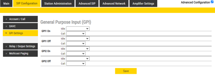
GPI Settings
GPIx On
- Idle: Call Destination
- Call: Hangup Call
GPIx Off
- Idle: Call Destination
- Call: Hangup Call
Relay/Output Settings
Details are described in this article: GPO Output configuration (ENA amplifier in SIP mode)
Station Administration
Change Password
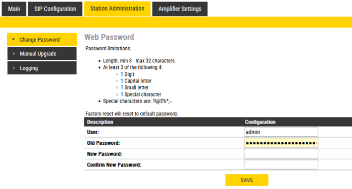
Go to Station Administration -> Change Password
Type in the old password and the new password, then click save.
Device GUI PIN
There is also an option to set a pin code for the Device GUI. A Read only-user and a Full Access-user can be enabled, or changing settings from the GUI can be disabled entirely.
The amplifier arrives with no pin code active by default.
Manual Upgrade
The software of the amplifier can be upgraded via the web interface. see Turbine_Software_Upgrade for details.
Logging
Logs can be useful for debugging and troubleshooting purposes. See Logging - IP Stations on how to enable and collect logs.
Amplifier Settings
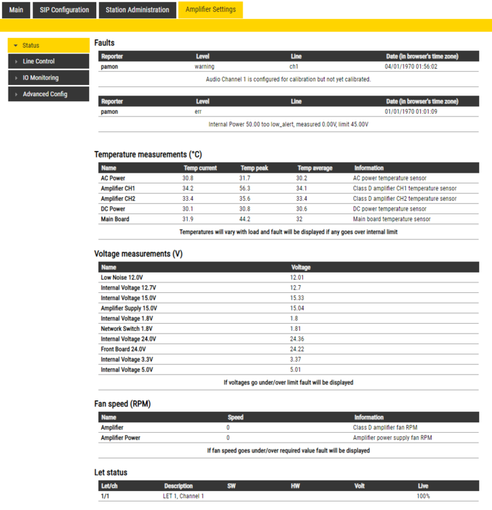
Status
- Faults
- Display currently active faults on amplifier
- The page is automatically refreshed each 10 seconds (can be manually refreshed)
- Only faults that are active for enabled monitoring options are visible
- If the page is empty there are no reported faults
- Temperature measurements
- Display different temperature levels
- Voltage measurements
- Display measured voltage levels for diagnostics
- Fan speed (RPM)
- Display the fan speed for the two fans inside the amplifier (Not applicable to the ENA2060 amplifier)
- Let status
- If there are Let configured for the amplifier the status will be displayed here
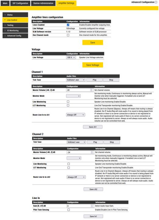
Line Control
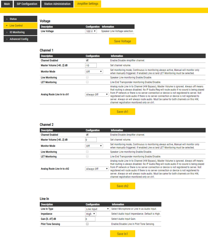
- Line Control Settings
Voltage options:
- Line Voltage choose speaker line voltage - 70V or 100V options
Channel 1/Channel 2 options:
- Channel Enabled will disable/enable selected channel, this shutdowns/starts channel amplifier and is not related to disabling channel registration (Station Main → Main Settings → Registration Settings → CH2/Audio in → Disabled)
- Master Volume in dB changes channel volume for digital audio
- Monitor Mode can be Off, Manual for manual monitor triggering and Continuous for continuous monitoring
- To get access to monitoring configuration options, either type of monitoring has to be enabled
- Analog Route Line In to ch - (only available when ln1 → Line In Type is Line Input) will analog route line in audio to channel output - this is HW Bypass
- On ENA hardware when enabled this option will disable digital audio playback (from IP) and has to be selected for both channels simultaneously
- Routing starts working when device boots
- On ENA hardware when enabled this option will disable digital audio playback (from IP) and has to be selected for both channels simultaneously
- Analog Routing Gain (only available when Analog Route Line In to ch is enabled) in dB offers setting gain when analog routing is selected, Master Volume values are not used. Setting goes from -6 to 0dB.
Line In options:
- Line In Type selects which input is used for audio input: Line in or Microphone
- Impedance changes line in impedance
- Gain changes line in gain
- Pilot Tone Sensing Enable/Disable Line In Pilot Tone Sensing
- Phantom Microphone (only available when Line In Type is Microphone Input) enables phantom power for microphone
Monitoring options
Available monitoring options when Monitoring is set to Continuous or Manual:
Channel 1/Channel 2:
- LET Monitoring enables Line End Transponder monitoring
- Line Monitoring enables Speaker Line Monitoring (SLM)
- Line Monitoring Options (only available when Line Monitoring is enabled)
- Detailed Line Fault Reporting will enable separate reporting of open and shorted, not available on all speaker line configurations
- Load Change monitor line load change
- Ground Fault monitor line ground fault
- Manual Monitoring Options (only available when Monitor Mode is Manual)
- Remove LET Faults when enabled LET faults will be removed when manual monitoring is finished
- Remove SLM Faults when enabled SLM faults will be removed when manual monitoring is finished
- Fault Report Options
- Report Faults Severity selects how are line faults reported on device GUI as critical (red exclamation sign) or warnings (yellow exclamation sign)
- Suspend Monitoring Options (only available when Monitor Mode is Continuous)
- When Suspended Monitoring is enabled, the amplifier will suspend the monitoring signal when there is a call on the channel to avoid false alerts and maintain audio quality.
- LET (only available when LET Monitoring is enabled)
- 10 LETs per channel can be added
- Failed Counter How many times LET should fail before error is reported
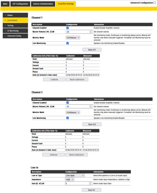
- Calibration Info (only available when channel monitoring is enabled, configured and saved)
- Calibrate command (35 seconds timeout) will attempt channel calibration
- Reset Calibration (3 seconds timeout) will reset channel calibration
- Measure (60 second timeout, only available if Monitor Mode is Manual and channel is successfully calibrated) will manual monitor channel for 60 seconds and report any faults detected
Testing
IO Monitoring
The ENA amplifier offers monitoring of the outputs and the inputs:
- RCOs
RCO is not supported for ENA amplifiers in SIP.
- RCIs
- RCI Config allows configuring the thresholds for when the RCI triggers. An RCI has an open voltage of 10V across the terminals. A resistor network is needed to ensure that RCI's can be monitored properly.
- Monitor RCI enables monitoring of RCI.
- Not Connected - When the voltage on the pin is higher than this threshold, it's set as Not Connected.
- Not Pressed - Low threshold for the RCI to be considered not pressed.
- Pressed - High threshold for the RCI to be considered pressed.
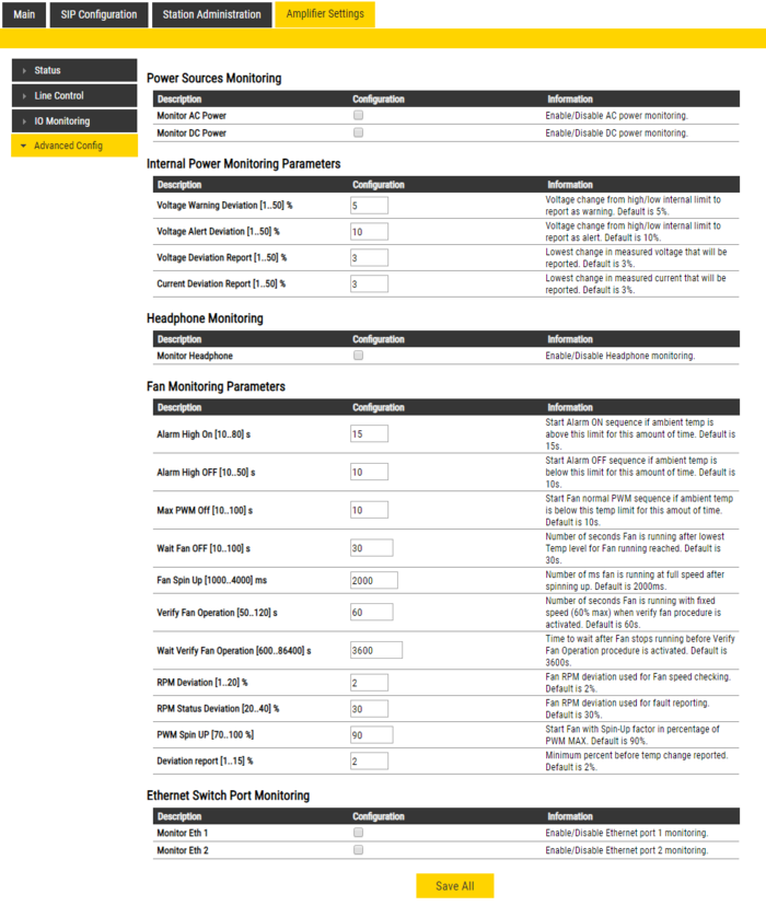
Advanced Config
Enable and configure various monitoring features.
- Internal Power Monitoring
- Monitor AC Power enable AC power monitoring
- Monitor DC Power enable DC power monitoring
- Internal Monitoring Parameters
- Voltage Warning Deviation Issue a warning if internal voltage changes more than configured percentage from reference voltage
- Voltage Alert Deviation Issue a alert if internal voltage changes more than configured percentage from reference voltage
- Voltage Deviation Report Report in GUI status bar if internal voltage changes more than configured percentage from reference voltage
- Current Deviation Report Report in GUI status bar if internal current changes more than configured percentage from reference voltage
- Headphone
- Monitor Headphone reports if headphone is disconnected
- Fan Amplifier
- Alarm High On starts alarm on sequence if ambient temp is above high limit for this amount of time
- Alarm High Off starts alarm off sequence if ambient temp is below high limit for this amount of time
- Max PWM Off starts fan normal PWM sequence if ambient temp is below high temp limit for this amount of time
- Wait Fan OFF number of seconds fan is running after lower temp level for fan running reached
- Fan Spin Up number of ms fan is running at full speed after spinning up
- Verify Fan Operation number of seconds fan is running with fixed speed (60% max) when verify fan procedure is activated
- Wait Verify Fan Operation time to wait after fan stops running before Verify Fan Operation procedure is activated
- RPM Deviation fan RPM deviation used for fan speed checking
- RPM Status Deviation fan RPM deviation used for GUI reporting
- PWM Spin UP start Fan with Spin-Up factor in percentage of PWM max
- Deviation report minimum percent before temp change reported
- Ethernet Switch
- Monitor Eth 1 monitor Ethernet switch port 1 cable connection
- Monitor Eth 2 monitor Ethernet switch port 2 cable connection


