Difference between revisions of "APC - AlphaCom Program & Clock Board"
From Zenitel Wiki
| Line 1: | Line 1: | ||
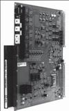
[[image:APC Program and Clock Board.jpg|thumb|100px|APC Program & Clock Board]] | [[image:APC Program and Clock Board.jpg|thumb|100px|APC Program & Clock Board]] | ||
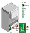
| − | + | [[image:APC board, connection and adjustment.jpg|thumb|right|100px|APC board, connection and adjustment]] | |
The '''APC board''' is mandatory in the AlphaCom E20 and E26 exchanges. It controls the back plane board clocking. It also supervises board temperatures and controls the speed of the fans. This board contains circuitry for 6 audio program feed channels with galvanic isolation. Easily accessible potentiometers at the front enable sensitivity control of the audio program input. The clock can be synchronized with (phase-locked to) an external clock. The board plugs into position 26 only. | The '''APC board''' is mandatory in the AlphaCom E20 and E26 exchanges. It controls the back plane board clocking. It also supervises board temperatures and controls the speed of the fans. This board contains circuitry for 6 audio program feed channels with galvanic isolation. Easily accessible potentiometers at the front enable sensitivity control of the audio program input. The clock can be synchronized with (phase-locked to) an external clock. The board plugs into position 26 only. | ||
| Line 16: | Line 16: | ||
* Power connector (6-pin socket source) for [[hot-plug|hot plug-in]] cable | * Power connector (6-pin socket source) for [[hot-plug|hot plug-in]] cable | ||
| − | |||
[[Category:AlphaCom E System]] | [[Category:AlphaCom E System]] | ||
| − | |||
| − | |||
== Technical Specification == | == Technical Specification == | ||
Revision as of 13:46, 15 August 2007
The APC board is mandatory in the AlphaCom E20 and E26 exchanges. It controls the back plane board clocking. It also supervises board temperatures and controls the speed of the fans. This board contains circuitry for 6 audio program feed channels with galvanic isolation. Easily accessible potentiometers at the front enable sensitivity control of the audio program input. The clock can be synchronized with (phase-locked to) an external clock. The board plugs into position 26 only.
Features
- System master clock (two-phase - 16.384 Mhz) and module reset
- Circuitry for 6 audio program feed channels
- Can be fed by any analog source
- Galvanic isolated input via 600 ohm transformer to avoid noise problems
- Adjustable sensitivity (gain)
- 6 alarm inputs
- 2 internal alarms
- Reset button
- Fan control
- Coded connector to ensure correct positioning in the module
- Power connector (6-pin socket source) for hot plug-in cable
Technical Specification
| Order Number: | 100 9301 000 |
|---|---|
| Operation Voltage: | 5, 15, 24, V DC |
| Dimensions (WxHxD) <br\><br\> | 10mm x 230mm x 263mm <br\> 0.39"x 8.97"x 10.26" <br\> Double Extended Europe Format |
| Sensitivity (adjustable) | 100 mV to 1 V |
| Frequency range with program reed | 200-15,000 Hz |
| Indicator: | Drives module status indicator on front panel |


