Difference between revisions of "IP-LCM Connections"
From Zenitel Wiki
| (32 intermediate revisions by 3 users not shown) | |||
| Line 1: | Line 1: | ||
| + | {{AEIPS}} | ||
== Connector overview == | == Connector overview == | ||
[[File:IPLCM Connectors.PNG|thumb|1000px|none|IP-LCM connectors]] | [[File:IPLCM Connectors.PNG|thumb|1000px|none|IP-LCM connectors]] | ||
== Inputs == | == Inputs == | ||
| − | + | The [[IP-LCM|IP-LCM module]] has 8 inputs. Each of them has a corresponding selector switch, with which one can select between a dry closing contact or an active input. | |
| − | * '''Left position''': The input requires an active signal | + | * '''Left position''': The input requires an active signal 12V to 48VDC. The input is galvanic isolated with an opto-coupler. Polarity as indicated on the drawing. |
* '''Right position''': The input requires a dry contact | * '''Right position''': The input requires a dry contact | ||
| + | |||
| + | ==== Connectors ==== | ||
| + | * without ferrule: 0.5mm-1.5mm / 20 AWG - 16 AWG | ||
| + | * with ferrule with plastic/metal collar: 0.75mm-1mm / 18 AWG - 17 AWG | ||
| + | |||
| + | <br> | ||
== Outputs == | == Outputs == | ||
| Line 12: | Line 19: | ||
Each output has a LED which indicates if the relay is active or not. | Each output has a LED which indicates if the relay is active or not. | ||
| − | Relay 5 to 8 has a corresponding output selector switch. With this switch one can select if the Contact Set #1 should provide dry contacts, or if it should forward power from the power forwarding connector. Contact Set #2 will always provide dry contacts, regardless of the position of the output selector switch. | + | Relay 5 to 8 has a corresponding output selector switch. With this switch one can select if the Contact Set #1 should provide dry contacts, or if it should forward power from the '''power forwarding''' connector. Contact Set #2 will always provide dry contacts, regardless of the position of the output selector switch. |
| − | + | * '''Left position''': '''Dry Contact''' mode. Contact Set #1 provides dry contacts. | |
| + | * '''Right position''': '''Power Forwarding''' mode. Contact Set #1 forwards power from the an external power supply connected to the IP-LCM unit. When the PSU is connected with the polarity as indicated in the drawing above, the "+" will appear on the Com terminal, and the "-" will appear on the NO-terminal when the relay is active. When the relay is in idle, the "-" will appear on the NC-terminal. | ||
| − | + | [[File:IP-LCM ContactSet.PNG|thumb|400px|none|IP-LCM relays]] | |
| − | |||
{{note|The external power supply is required only when you need to forward power via relays 5 - 8. This is the only purpose of the power supply. }} | {{note|The external power supply is required only when you need to forward power via relays 5 - 8. This is the only purpose of the power supply. }} | ||
'''Relay contact ratings''': | '''Relay contact ratings''': | ||
| − | * '''Outputs''': DPDT (Double Pole Double Throw). NO (Normal Open), NC (Normal Closed), COM (Common) | + | ** '''Relay Outputs''': DPDT (Double Pole Double Throw). NO (Normal Open), NC (Normal Closed), COM (Common) |
| − | * '''Switched | + | * '''Relay 1 - 4 (both contact sets) and Relay 5-8 (contact set #2)''': |
| − | * '''Switched | + | ** '''Switched Voltage''': < 250VAC Rated (400VAC Max) |
| − | * '''Switching Current''': < 8A rated ( | + | ** '''Switched Power''': < 2000 VA max |
| + | ** '''Switching Current''': < 8A rated (12A max for 1 second) | ||
| + | * '''Relay 5-8 (contact set #1)''': | ||
| + | ** '''Dry Contact''' mode: 100VAC/1A | ||
| + | ** '''Power Forwarding''' mode: 30V/100mA | ||
| + | ==== Connectors ==== | ||
| + | * without ferrule: 0.5mm-1.5mm / 20 AWG - 16 AWG | ||
| + | * with ferrule with plastic/metal collar: 0.75mm-1mm / 18 AWG - 17 AWG | ||
| + | ==Related== | ||
| + | [[Turbine Compact series board connectors]] | ||
| − | + | [[Category: Turbine Connections]] | |
Latest revision as of 15:17, 23 June 2023
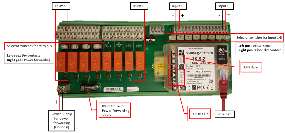
Connector overview
Inputs
The IP-LCM module has 8 inputs. Each of them has a corresponding selector switch, with which one can select between a dry closing contact or an active input.
- Left position: The input requires an active signal 12V to 48VDC. The input is galvanic isolated with an opto-coupler. Polarity as indicated on the drawing.
- Right position: The input requires a dry contact
Connectors
- without ferrule: 0.5mm-1.5mm / 20 AWG - 16 AWG
- with ferrule with plastic/metal collar: 0.75mm-1mm / 18 AWG - 17 AWG
Outputs
There are 8 relays, each with two sets of changeover contacts (DPDT). The contact terminals, Normally Open (NO), Normally Closed (NC) and Common (COM), are labeled in the silk print of the PCB.
Each output has a LED which indicates if the relay is active or not.
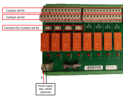
Relay 5 to 8 has a corresponding output selector switch. With this switch one can select if the Contact Set #1 should provide dry contacts, or if it should forward power from the power forwarding connector. Contact Set #2 will always provide dry contacts, regardless of the position of the output selector switch.
- Left position: Dry Contact mode. Contact Set #1 provides dry contacts.
- Right position: Power Forwarding mode. Contact Set #1 forwards power from the an external power supply connected to the IP-LCM unit. When the PSU is connected with the polarity as indicated in the drawing above, the "+" will appear on the Com terminal, and the "-" will appear on the NO-terminal when the relay is active. When the relay is in idle, the "-" will appear on the NC-terminal.

|
The external power supply is required only when you need to forward power via relays 5 - 8. This is the only purpose of the power supply. |
Relay contact ratings:
- Relay Outputs: DPDT (Double Pole Double Throw). NO (Normal Open), NC (Normal Closed), COM (Common)
- Relay 1 - 4 (both contact sets) and Relay 5-8 (contact set #2):
- Switched Voltage: < 250VAC Rated (400VAC Max)
- Switched Power: < 2000 VA max
- Switching Current: < 8A rated (12A max for 1 second)
- Relay 5-8 (contact set #1):
- Dry Contact mode: 100VAC/1A
- Power Forwarding mode: 30V/100mA
Connectors
- without ferrule: 0.5mm-1.5mm / 20 AWG - 16 AWG
- with ferrule with plastic/metal collar: 0.75mm-1mm / 18 AWG - 17 AWG


