AudioCodes MP114/118, v5.4 and higher
From Zenitel Wiki

This article describes the setup of the AlphaCom E system and the AudioCodes MP-114/118 SIP Gateway, firmware version 5.4 and 5.6. The article covers the most common features used in an AlphaCom ↔ AudioCodes interconnection.
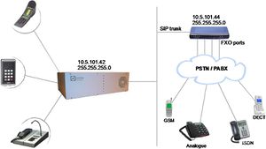
The configuration of AlphaCom E with SIP gateway includes the
following steps:
Using AlphaWeb
- Assign IP address to the AlphaCom Ethernet port
- Insert SIP Trunk licenses
- Firewall (filter) settings
Using AlphaPro
- Create a SIP Trunk Node
- Define the AlphaCom / SIP routing
- Create prefix numbers
- Update the exchange
AlphaCom Configurations
AlphaWeb Configurations
Assign IP adress to the AlphaCom E Ethernet port(s)
- Log on to AlphaWeb and enter a valid IP address on the Ethernet port.
In the example below, Ethernet port 1 is used. Consult your network administrator to obtain the IP address.
Insert SIP Trunk licenses
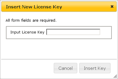
Log on to AlphaWeb and install the SIP Trunk license.
Firewall (filter) settings
Enable the SIP protocol and VoIP Audio on the desired Ethernet port (default enabled for Ethernet port1).
AlphaPro Configuration
Create a SIP Trunk Node
From the AlphaPro main menu, use the ‘+’ button next to the ‘Select Exchange’ dropdown list to create a new exchange. The exchange type must be set to ‘SIP Node’.
Set the parameters as follows:
The SIP Trunk IP address must be identical to the IP address of the SIP Gateway.
Note: If the AlphaCom is configured with a SIP Registrar node in addition to the SIP Trunk node, the SIP Registrar node must have a lower node number than the SIP Trunk node.
Define the AlphaCom / SIP routing
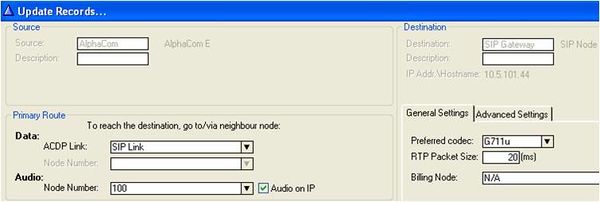
In Exchange & System > Net Routing use the Insert button to create a route between the AlphaCom and SIP Gateway. Set Preferred codec to G711u and RTP Packet Size to 20 ms.
Create Prefix number
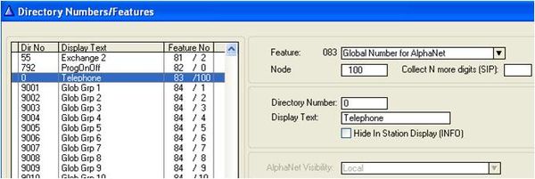
The directory number (prefix) used to access the telephone line must be programmed in the AlphaCom directory table with feature 83 and Node = SIP Trunk node number (100 in this example). In the example below the default directory number 0 has been modified to be used as a prefix.
Update the exchange
Log on to the exchange and update the exchange by pressing the SendAll button. Reset the exchange after the send operation is finished.
Audiocodes MP-114/118 Configuration
Configure Network Parameters
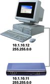

The AudioCodes MP-114/118 VoIP Gateway comes with default network parameters (factory default parameters).
Before you can set up the gateway in the network, you have to change the default IP address to a fixed IP address in your network environment. The unit is configured from a web browser, e.g. Internet Explorer or Navigator. Consult the network administrator to get the correct IP address.
Follow these steps:
- Load factory network parameters and reset the username and password to its default settings (username: Admin, password: Admin) by following these three steps:
1. Disconnect the Ethernet cable from the device.
2. With a paper clip or any other similar pointed object, press and hold down the Reset button (located on the rear panel) for about six seconds; the Fail LED turns red and the device restores to factory default settings.
3. When the Fail LED turns off, reconnect the Ethernet cable to the device.
- The VoIP Gateway will now get the IP address 10.1.10.11, subnet mask 255.255.0.0.
Change the IP address of your PC to 10.1.10.12, subnet mask 255.255.0.0.
Connect the LAN port of the PC to the Ethernet port of the Gateway. Use a crossed cable or connect the PC and the VoIP Gateway to a common switch using straight cables.
- Start your Web Browser and type 10.1.10.11 in the URL field.
- Type in user name Admin and password Admin. (Case-sensitive!)
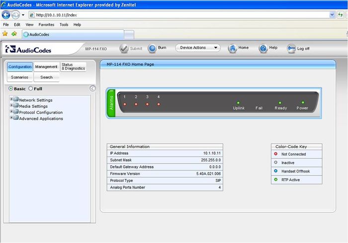
The Home page of the Web Interface:
IP Configuration
- In the 'IP Settings' page (Configuration tab > Network Settings menu > IP Settings page item) enter the IP Address, Subnet Mask and optionally the Default Gateway Address of the AudioCodes Gateway.
This IP address must be identical to the IP address of the SIP Trunk Node created in AlphaPro.
- Click Submit to apply the changes.
Note: The IP address is immediately changed when pressing Submit, but it is not permanently stored. Without resetting or powering off the device, you need to log on to the Gateway using its new IP address in order to Burn the new IP address to flash:
- Disconnect the PC from the Gateway.
- Reconnect the Gateway and PC to the LAN. The PC and Gateway must be on the same sub-net.
- Restore the PC’s IP address and subnet mask to what they originally were, and re-access the Gateway using the new assigned IP address.
- Click Burn to permanently apply the changes.
SIP Parameters
- In the 'Proxy & Registration' page (Configuration tab > Protocol Configuration menu > Protocol Definition submenu > Proxy & Registration page item) set the ‘Use Default Proxy’ field to ‘Yes’.
- 'Proxy Name' must be blank
- 'Gateway Name' must be blank
- Click the Proxy Set Table button. In the ‘Proxy Address’ field enter the IP address of the AlphaCom.
- Set 'Transport Type' to 'UDP'.
- Press Submit to save changes
Audio Codec
- Select the voice coder in 'Coders Table' page (Configuration tab > Protocol Configuration menu > Protocol Definition submenu > Coders page item). Choose G.711U-law Coder Name, 20 ms Packetization Time and Silence Suppression Disabled.
- Press Submit to save changes
About Saving Changes
The Submit button will save the data to the running volatile memory. The changes take effect on-the-fly. The changes will not survive hardware reset or power off.
To permanently save the configuration data, store the data to flash memory by selecting Burn from the Tool Bar.
Note: Parameters proceeded by a yellow lightning symbol is not changeable on-the-fly and require that the device is reset.
Backup and Restore
The configuration of the AudioCodes Gateway can be stored to a file on your PC.
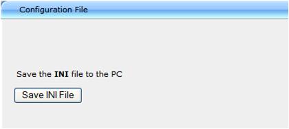
From the Tool Bar select Device Actions -> Save Configuration File. Select Save INI File to save the configuration to the PC, and select Load INI File to upload a configuration file to the SIP Gateway.
AlphaCom to Telephone Network
There are two ways of selecting a FXO line from the AlphaCom.
- Group Hunt, where a prefix is dialed and you are connected to one out of several lines
- Direct FXO line selection, where there is one prefix assigned for each of the FXO lines.
The two methods can be combined.
Alternative 1: Group Hunt
Dial a prefix and get connected to a free FXO line.
Hunt Group Settings
- In the 'Hunt Group Settings' page (Configuration tab > Protocol Configuration menu > Hunt/IP Group submenu > Hunt Group Settings page item) set the ‘Hunt Group ID’ field to ‘1’ and ‘Channel Select Mode’ to ‘Cyclic Ascending’.
IP to Hunt Group Routing When dialing the prefix from AlphaCom, the call needs to be routed to the appropriate Hunt Group ID associated with the FXO ports. In the example below the call is routed to group hunt ID 1. (Configuration tab > Protocol Configuration menu > Routing Tables submenu > IP to Trunk Group Routing page item)
Endpoint Phone Number
In the ‘Endpoint Phone Number Table’ page the FXO lines are linked to the prefix in AlphaCom and to the hunt group ID. (Configuration tab > Protocol Configuration menu > Endpoint Number submenu > EndPoint Phone Number page item).
In the example below all four FXO lines belong to Hunt Group ID 1. When dialing 0 on an intercom station the first available line will be granted. Directory number 0 must be programmed in the AlphaCom directory table with feature 83/<node>. See paragraph 2.2.3.
If there are unused lines, leave the fields for that line blank.
Alternative 2: FXO Line Select
In installations with different types of equipment connected to the various FXO lines the user must be able to select which FXO port to use. On a ship, for instance, there could be a mix of shore lines, GSM interface and Satelitte lines. Line selection is achieved by assigning each port a unique Phone Number in the Endpoint Phone Number Table. These directory numbers must be programmed in the AlphaCom directory table with feature 83/<node>. See paragraph 2.2.3.
Replace “0” with four lines, “41” to “44”.
In this table the four FXO lines are selected by dialing 41 – 44 If there are unused lines, leave all fields for that line blank. Group hunt is not used in this call mode, and the IP to Hunt Routing Table must be empty.
Telephone Network to AlphaCom
You can choose between three different ways of handling an incoming call from the telephone line:
- Selective Dialing
- Automatic Dialing
- Delayed Automatic Dialing
Selective Dialing
A second dial tone will be presented when calling in, and the user can dial the desired intercom number. The fields in the ‘Automatic Dialing’ page item must be left blank (Default setting). (Configuration tab > Protocol Configuration menu > Endpoint Settings submenu > Automatic Dialing page item).
In this mode the gateway collects digits from the line, and sets up the call towards the AlphaCom when a predefined number of digits are collected and no more digits are received within a preset time (default 4 seconds), or when the ‘#’ key is dialed.
In the 'DTMF & Dialing' page (Configuration tab > Protocol Configuration menu > Protocol Definition submenu > DTMF & Dialing page item) select ‘Advanced Parameter List’ in order to view all parameters, and set ‘Max Digits In Phone Num’ equal to the number of digits used on the AlphaCom stations, normally 3 or 4. The parameter ‘Inter Digit Timeout for Overlap Dialing’ specifies the waiting time for more digits before setting up the call.
Automatic Dialing (Call to Switchboard)
When calling in, the call will automatically be connected to a predefined intercom number.
- Enter the intercom number in the ‘Destination Phone Number’ field in the ‘Automatic Dialing’ page item. Set ‘Auto Dial Status’ to ‘Enable’. (Configuration tab > Protocol Configuration menu > Endpoint Settings submenu > Automatic Dialing page item).
In the example above, incoming calls on line 1 are routed to station 103, calls on line 2 are routed to station 101, and calls on line 3 and 4 are routed to RingingGroup 6701.
Delayed Automatic Dialing
If ‘Auto Dial Status’ is set to ‘Hotline’, a second dial tone will be presented when calling in, allowing the user to dial a number. But if no digits are pressed within the ‘Hotline Dial Tone Duration’ time, the number in the Destination Phone Number is automatically dialed.
The ‘Hotline Dial Tone Duration’ can be changed from the 'DTMF & Dialing' page item (Configuration tab > Protocol Configuration menu > Protocol Definition submenu > DTMF & Dialing page item). Select the ‘Advanced Parameter List’. The default value is 16 seconds.
Caller ID
Use the ‘Caller Display Information’ page to send display information to the intercom station that receives the call. (Configuration tab > Protocol Configuration menu > Endpoint Settings submenu > Caller Display Information page item).
The prefix code entered in the End Point Phone Number Table will be shown together with the text in Caller ID/Name.
If Caller ID name is detected on the FXO line, this will be used instead of the Caller ID name in the table above. Display the Navigation Tree in Full View. Caller ID from FXO line must be enabled in Configuration tab > Protocol Configuration menu > SIP Advanced Parameters submenu > Supplementary Services page item.
- Set ‘Enable Caller ID’ to ‘Enable’ and choose the ‘Caller ID Type’ as used by the PSTN supplier. Check with the local telephone company to find the ‘Caller ID Type’ used.
Far end disconnect (FED)
Far End Disconnect refers to methods for detecting that a remote party has hung up. The far end disconnect signal is not mandatory and this could create problems. If the Far End Disconnect signal is not sent to or properly detected by the SIP Gateway, the connection will not be released by the unit, thus freezing the FXO line in the off hook state.
Call Termination options in the SIP Gateway
The following methods for call termination are supported by the AudioCodes MP-114/118. Note that the used disconnection methods must be supported by the CO (Central Office) or to PBX (Private Branch Exchange).
- Detection of polarity reversal / current disconnect
- Detection of Busy / Dial tones
- Timeout of Conversation
- Detection of silence (NOT recommended, could lead to unwanted disconnection of calls)
Detection of polarity reversal / current disconnect
This is the recommended method. The call is immediately disconnected after polarity reversal or current disconnect is detected on the Tel side (assuming the PBX / CO produces this signal).
- Display the Navigation Tree in Full View. Enable the relevant detection method in Configuration tab > Protocol Configuration menu > SIP Advanced Parameters submenu > Advanced Parameters page item.
Note:
In the UK, if you are using BT and are having problems with AudioCodes not detecting current disconnect hangups, your PSTN line might have the wrong specifications for the AudioCodes to detect hangups.
Contact BT and ask what the current DCT (Disconnect Clear Time) setting is for your phone line. It should be around 800ms.
If this is the case, you also need to adjust the DCT setting on the AudioCodes as the default value is 900ms.
Add this parameter to the .ini config file:


CURRENTDISCONNECTDURATION = 800
Detection of Busy / Dial tones
The call is immediately disconnected after Busy or Dial tone is detected on the Tel side (assuming the PBX / CO produces this tone). This method requires the correct tone frequencies and cadence to be defined in the Call Progress Tones (CPT) file of the SIP Gateway. If these frequencies are not known, define them in the CPT file (the tone produced by the PBX / CO must be recorded and its frequencies analyzed). This method is slightly less reliable than the previous one.
- Open the ‘FXO Settings’ page item in Configuration tab > Advanced Applications menu > FXO Settings page item and enable the relevant detection method.
Call Progress Tones (CPT)
The Detection of Busy / Dial tones method requires the correct tone frequencies and cadence (on/off sequence) to be defined in the Call Progress Tones (CPT) file of the SIP gateway. These tones are region specific and telephone exchange dependent.
The Call Progress Tones (CPT) configuration file is a binary file (with the extension .dat).
You can either use:
- a CPT file with the most common tone patterns available from the download site
- one of the supplied CPT (dat) files found on the CD provided with the gateway
- construct your own file by adding new tones to the CPT file
Load a Call Progress Tones (dat) file to the SIP gateway:
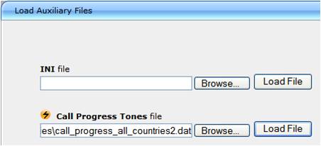
- Select Management tab > Software Update menu > Load Auxiliary Files page item.
- Click the Browse button and navigate to the folder that contains the file you want to load
- Click the file and click the Open button; the name and path of the file appear in the field beside the Browse button
- Click the Load File button
- Burn the configuration so the file can be available after a power failure
- Reset the SIP Gateway for the changes to take effect
For more detailed information regarding Call Progress Tones please refer to the AudioCodes User's Manual found on the CD supplied with the unit.
Timeout of Conversation
As an additional safety to prevent lines from accidentally locking up, it is recommended to enable a timeout of conversation.
The ‘Max Call Duration’ defines the maximum call duration in minutes. If this time expires, both sides of the call are released (IP and Tel). The valid range is 0 to 120. The default is 0 (no limitation).
- Display the Navigation Tree in Full View. Enable the ‘Max Call Duration’ in Configuration tab > Protocol Configuration menu > SIP Advanced Parameters submenu > Advanced Parameters page item.
Message log
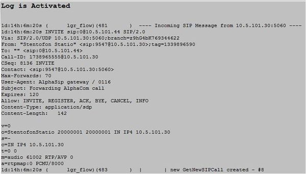
The 'Message Log' page displays Syslog debug messages sent by the device. You can select the Syslog messages in this page, and then copy and paste them into a text editor such as Notepad. This text file (txt) can then be sent to Technical Support for diagnosis and troubleshooting.
Note: It's not recommended to keep a Message Log session open for a prolonged period. This may cause the device to overload. For prolonged (and detailed) debugging, use an external Syslog server.
To activate the Message Log, take these 3 steps:
- In the 'Advanced Parameters' (Configuration tab > Protocol Configuration menu > SIP Advanced Parameters submenu > Advanced Parameters page item), set the parameter 'Debug Level' to 6. This parameter determines the Syslog logging level in the range 0 to 6, where 6 is the highest level.
- Open the 'Message Log' page (Status & Diagnostics tab > Status & Diagnostics menu > Message Log page item). Now the 'Message Log' page is displayed and the log is activated.
The displayed logged messages are color coded as follows:
- Yellow - fatal error message
- Blue - recoverable error message (i.e., non-fatal error)
- Black - notice message
- To clear the page of Syslog messages, in the Navigation tree, click the page item Message Log again; the page is cleared and new messages begin appearing.
To stop the Message Log, take this step:
- Close the page by accessing any another page in the Web interface.
Miscellaneous features
Incoming Calls in Private

Incoming calls from the telephone line can be forced to be in private ringing mode, independent of the private/open switch of the intercom station.
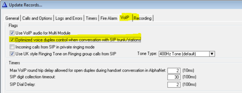
Check the flag Incoming calls from SIP in private ringing mode in AlphaPro, (Exchange & System > System > VoIP).
Door Opening Feature
During a conversation between a door station and a telephone, the telephone operator can activate the Door Opening feature in the AlphaCom by pressing digit 6.
Note!
The SIP Gateway is automatically put in Class of Service 15. This group does not have the option for remote door opening
enabled by default. In AlphaPro go to Class of Service, select number 15 (Outside Telephones), press change and locate
number 58 in the "Not Valid" list. Highlight Feature 58 and use the arrow keys to move it to the "valid" list.
SIP Gateway Configuration
To enable digit actions from the telephone line during conversation, set ‘1st Tx DTMF Option’ to ‘INFO(Cisco)’ in the 'DTMF & Dialing' page. (Configuration tab > Protocol Configuration menu > Protocol Definition submenu > DTMF & Dialing page item).
AlphaCom configuration
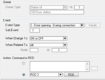
The Door Opening feature is programmed in the Event Handler. There are two separate events for the door opening feature, depending on who is the calling side:
- calling from the telephone to the door
- calling from the door to the telephone
Calling from the telephone to the door:
The Standard door opening event is used.
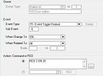
Calling from the door to the telephone:
When the phone presses digit 6, the event type Event Trigger Feature (15) is reported, with the digit 6 as sub event. The calling AlphaCom station is Event Owner, and called SIP phone number and node number is Related To. The RCO pulse time is specified as an additional parameter in the RCO action string, i.e. RCO 3 ON 20 means pulse RCO 3 for 2 seconds.
M-Key Control from Telephone Network
The ‘*’ and ‘#’ buttons on the telephone can be used to control M-key function (simplex audio) ON or OFF:
- Press the ‘*’-key briefly and the M-key is turned ON
- Press the ‘#’-key briefly and the M-key is turned OFF
This can be useful for group call announcement from the telephone. The feature is enabled by setting 1st Tx DTMF Option to INFO(Cisco) in Protocol Management > Protocol Definition > DTMF & Dialing.
Transmit '*' and '#' from AlphaCom
The DTMF signals ‘*’ and ‘#’ will be transmitted to the line when DAK 0 (*) and DAK 1 (#) is pressed during a telephone conversation. No programming is required.
Voice Switching in Noisy Environment
If the intercom station is located in a noisy environment, it might be difficult to switch the voice direction from the telephone towards the intercom station. However, there is a setting in the AlphaCom to overcome this problem. In AlphaPro, Exchange & System > System > VoIP, set the parameter Optimized voice duplex control when conversation with SIP trunk/stations
When this flag is set, the initial voice direction is forced to be from the intercom towards the telephone. When the phone operator starts to speak, the voice direction will switch towards the intercom station, regardless of the level of the audio signal from the intercom station. As soon as the phone operator stops speaking, the voice direction will switch back to the initial direction.
Make sure that the Echo Canceller is enabled in the SIP Gateway. (Configuration tab > Media Settings menu > Voice Settings page item > Echo Canceller = Enabled).
Country Settings
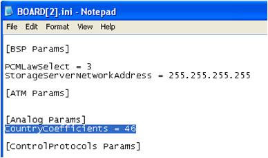
The Line Characteristics (AC impedance matching, hybrid balance, Tx & Rx frequency response, Tx & Rx Gains, ring detection threshold, DC characteristics) should be set according to country of origin. Some of the SIP Gateway parameters are configurable through the ini configuration file only (and not via the Web). The CountryCoefficients parameter that determines the line characteristics must be configured via the ini configuration file.
- Procedure to modify the ini file:
- Get the ini file from the gateway using the Embedded Web Server. From the Tool Bar select Device Actions -> Save Configuration File. Select Save INI File to save the configuration to the PC:
- Open the file (e.g. in Notepad) and add anywhere in the file the line
CountryCoefficients = xx
- where xx is the country code found below; save and close the file. The example below shows the settings for Norway (46).
- Load the modified ini file back to the gateway (using the button Load INI File).
This method preserves the programming that already exists in the device, including special default values that were preconfigured when the unit was manufactured.
Country codes
The default value is 70 (United States).
| Argentina | = 0 |
| Australia | = 1 |
| Austria | = 2 |
| Bahrain | = 3 |
| Belgium | = 4 |
| Brazil | = 5 |
| Bulgaria | = 6 |
| Canada | = 7 |
| Chile | = 8 |
| China | = 9 |
| Colombia | = 10 |
| Croatia | = 11 |
| Cyprus | = 12 |
| Czech_Republic | = 13 |
| Denmark | = 14 |
| Ecuador | = 15 |
| Egypt | = 16 |
| El Salvador | = 17 |
| Finland | = 18 |
| France | = 19 |
| Germany | = 20 |
| Greece | = 21 |
| Guam | = 22 |
| Hong_Kong | = 23 |
| Hungary | = 24 |
| Iceland | = 25 |
| India | = 26 |
| Indonesia | = 27 |
| Ireland | = 28 |
| Israel | = 29 |
| Italy | = 30 |
| Japan | = 31 |
| Jordan | = 32 |
| Kazakhstan | = 33 |
| Kuwait | = 34 |
| Latvia | = 35 |
| Lebanon | = 36 |
| Luxembourg | = 37 |
| Macao | = 38 |
| Malaysia | = 39 |
| Malta | = 40 |
| Mexico | = 41 |
| Morocco | = 42 |
| Netherlands | = 43 |
| New_Zealand | = 44 |
| Nigeria | = 45 |
| Norway | = 46 |
| Oman | = 47 |
| Pakistan | = 48 |
| Peru | = 49 |
| Philippines | = 50 |
| Poland | = 51 |
| Portugal | = 52 |
| Romania | = 53 |
| Russia | = 54 |
| Saudi_Arabia | = 55 |
| Singapore | = 56 |
| Slovakia | = 57 |
| Slovenia | = 58 |
| South_Africa | = 59 |
| South_Korea | = 60 |
| Spain | = 61 |
| Sweden | = 62 |
| Switzerland | = 63 |
| Syria | = 64 |
| Taiwan | = 65 |
| TBR21 | = 66 |
| Thailand | = 67 |
| UAE | = 68 |
| United_Kingdom | = 69 |
| UnitedStates | = 70 |
| Yemen | = 71 |
Feature Guide

- Make a call from an intercom station: Dial prefix – wait for the dial tone – dial phone number
- When pressing digits during connection, DTMF digits are sent (Call center etc.)
- The DTMF signals ‘*’ and ‘#’ will be transmitted when pressing DAK 1 (*) and DAK 2 (#)
- A complete phone number can be stored under a DAK key or a substation call button.
- Program DAK key from station:
784 + <prefix> + <phone number> + M + DAK key
Example: 784 + 0 + 40002500 + M + DAK key
- Program from AlphaPro:
I <prefix> P <phone number>
Example: I 0 P 40002500
Call Transfer
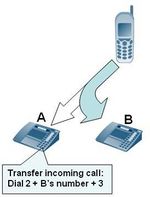
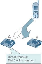

- Incoming calls from the line can be transferred to another station
During conversation, dial on the keypad:
- 2 + <intercom station> + 3
From a preprogrammed DAK:
- D 2 I 104 M M D 3
Outgoing calls to the line can be transferred to another station
During conversation, dial on the keypad:
- DAK9 + 2 + <intercom station> + 3
Option: Blind Transfer
- In AlphaPro, Directory & Features menu, modify the Inquiry feature 2 from default feature 55/0 to feature 55/1.
- During conversation, dial on the keypad:
- 2 + <intercom station>
Call Forwarding
An intercom call can be forwarded to a telephone
From keypad:
- 71 + 0 + <phone number> + M
From preprogrammed DAK:
- I 71 I 0 P 40002500
Search List
A telephone number can be included in the Search List of a station.
Format:
- I <prefix> P <phone number>
- Example: I 0 P 40002500
Customizing the web interface logo
In a few easy steps its possible to change the logo that is seen in the top left corner in the Audiocodes web interface.

- Access the device's web interface.
- In the URL field, append the case-sensitive suffix ‘AdminPage’ to the IP address (e.g. http://10.1.229.17/AdminPage); the 'Admin' page appears.
- On the left panel, click 'Image Load to Device'.
- Click the Browse button, and then navigate to the folder in which the logo image file that you want to use is located.
- Click the Send File button; the image file uploads to the device. When loading is complete, the page is automatically refreshed and the uploaded logo image is displayed in the Web interface's title bar.
- If you want to modify the width of the image, in the 'Logo Width' field, enter the new width (in pixels) and then click the Set Logo Width button.
- Save the image by pressing the 'Burn' button located on the top menu bar in the mainpage.
One Stage dialing
When interfacing to e.g. PABX's using the AudioCodes MP11x, there is often a requirement to have an integrated number plan. E.g. in order to call PABX extension 4529 from an intercom station one should dial the number 4529, and not use prefix (say 0 + 4529). To achive this one can use one-stage dialing (also called "enbloc dialing") instead of the default two-stage dialing (also called "overlap dialing").
The default dialing mode is two-stage dialing, and that is what is described earlier in this article. When two-stage dialing is enabled, the gateway seizes one of the PSTN/PBX lines without performing any dialing, connects the AlphaCom station to the PSTN/PBX, and all further signaling (dialing and Call Progress Tones) is performed directly with the PBX without the gateway's intervention.
When one-stage dialing is enabled, the gateway seizes one of the available lines, and dials the destination phone number received in the INVITE message from the AlphaCom. The digit collection is done in the AlphaCom.
AudioCodes Configuration
The AudioCodes gateway should be configured as described earlier in this article, but with the following modifications and additions:
- In the ‘Endpoint Phone Number Table’ page the FXO lines are linked to the hunt group ID and a Telephone Profile ID.
(Configuration tab > Protocol Configuration menu > Endpoint Number submenu > EndPoint Phone Number page item).
- If there are unused lines, leave the fields for that line blank.
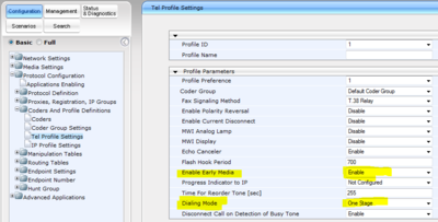
- In the ‘Tel Profile Settings' page, select Profile ID 1, and enable Early Media and set Dialing Mode to One-Stage.
(Configuration tab > Protocol Configuration menu > Coders and Profile Definitions submenu > Tel Profile Settings page item).
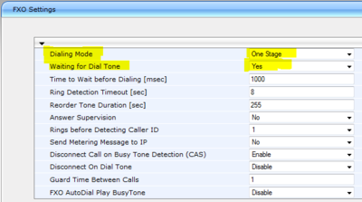
- In the 'FXO Settings' page, enable One-Stage dialing and 'Wait for dialtone'.
(Configuration tab > Advanced Applications menu > FXO Settings page item).
AlphaCom Configuration
The AlphaCom should be configured as described earlier in this article, but with the following modifications and additions:
When using one-stage dialing, the telephone number can be dialed in different ways:
- Prefix number: Dial Prefix + Phone number. E.g. 0 + 345678. Phone number 345678 will be dialed.
- Integrated Prefix number: Dial Prefix + Phone number. The prefix will be included as a part of the called telephone number. E.g. 5 + 345678. Phone number 5345678 will be dialed.
- Global number: Dial the phone number without using prefix. E.g dial 3456.
- Short number: Dial a short number, which is configured to dial a full telephone number. E.g. dial 345 to call telephone number 7654321.
Prefix number
The directory number must be programmed in the AlphaCom directory table with feature 81 and Node = SIP Trunk node number (100 in this example). In the field “Parameter 2/Collect N more digits (SIP)” you must enter the maximum number of digits in a phone number.
When the prefix is dialed, the AlphaCom will wait for more digits. When the number of digits specified in the “Parameter 2/Collect N more digits (SIP)” is collected, an INVITE message is sent to the AudioCodes gateway. If fewer digits are entered, the AlphaCom will time out after 3 seconds, and the INVITE message will be sent. You can also terminate the digit collection by pressing the M-key. The INVITE message will then be sent immediately.
In the example below the directory number 0 is used as a prefix.
- 0 + 12345678: Telephone number 12345678 will be called
- 0 + 1234: After a 3 second timeout, telephone number 1234 will be called
- 0 + 1234 + M: Telephone number 1234 will be called as soon as M-key is pressed
Integrated Prefix number
The directory number must be programmed in the AlphaCom directory table with feature 83 and Node = SIP Trunk node number (100 in this example). In the field “Parameter 2/Collect N more digits (SIP)” you must enter the maximum number of digits in a phone number.
When the prefix is dialed, the AlphaCom will wait for further digits. When the number of digits specified in the “Parameter 2/Collect N more digits (SIP)” is collected, an INVITE message is sent to the AudioCodes gateway. If fewer digits are entered, the AlphaCom will time out after 3 seconds, and the INVITE message will be sent. You can also terminate the digit collection by pressing the M-key. The INVITE message will then be sent immediately.
In the example below the directory number 57 is used as a prefix.
- 57 + 12345678: Telephone number 5712345678 will be called
- 57 + 1234: After a 3 second timeout, telephone number 571234 will be called
- 57 + 1234 + M: Telephone number 571234 will be called
Global number
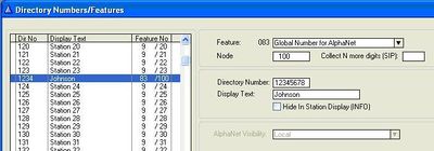
The directory number must be programmed in the AlphaCom directory table with feature 83 and Node = SIP Trunk node number (100 in this example). The field “Parameter 2/Collect N more digits (SIP)” must be left blank.
When the global number is dialed, the AlphaCom will immediately send an INVITE message to the AudioCodes gateway.
In the example below the directory number 12345678 is defined as a global number. When dialing this number an INVITE message is sent to the AudioCodes gateway, instructing it to call this phone number.
Short number
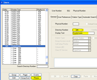
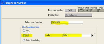
The configuration example below shows you how to create short number 345 to dial phone number 7654321.
- In AlphaPro, Users & Stations, select user 553 or higher
- Enter the short number and text
- Press the button Phone
- Enter the telephone number
- Set "Short number mode" = SIP
- Set "Node" = the SIP trunk node
Troubleshooting
Factory Reset by using BootP utility
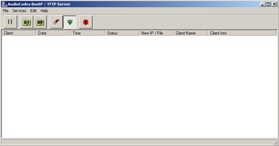
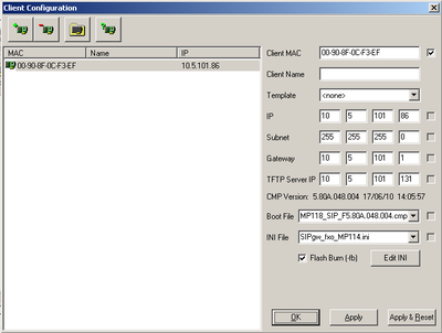
If the factory reset for some reason seem to fail, and you end up with all LED's lit in the MP11x, then it is no longer possible to contact the MP11x using a known IP address. A possible rescue is to use the AudioCodes' BootP program. This program accesses the MP11x using its MAC address and uploads a selected firmware file (cmp) and configuration file (ini file).
The BootP program, the cmp-file and the ini-file can be downloaded from the download site.
- Install and run BootP
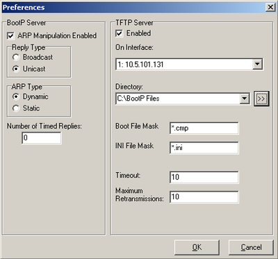
- Click Edit -> Preferences
- Set the TFTP server (your computer) and the directory where the firmware (.cmp) and .ini files are stored
- Click OK
- Click Service -> Clients
- Enter the MAC address and set the IP settings that you want the device to have. Also make sure that the boot file (firmware) and .ini file is selected
- Click Apply&Reset then OK


