IP-ARIO Configuration: Difference between revisions
From Zenitel Wiki
No edit summary |
|||
| (8 intermediate revisions by 2 users not shown) | |||
| Line 1: | Line 1: | ||
{{A}} | {{A}} | ||
=== | ==Main Settings == | ||
The IP-ARIO unit features an embedded web server, which allows users to log in via a standard web browser. At commissioning, the IP-ARIO unit needs to be configured to enable it to subscribe to an AlphaCom server/exchange. To do this, your PC and the IP-ARIO unit have to be connected together via a PoE switch using network cables: | === Settigs via the web interface === | ||
The [[IP-ARIO|IP-ARIO unit]] features an embedded web server, which allows users to log in via a standard web browser. At commissioning, the IP-ARIO unit needs to be configured to enable it to subscribe to an AlphaCom server/exchange. To do this, your PC and the IP-ARIO unit have to be connected together via a PoE switch using network cables: | |||
* Connect the PC to the PoE switch | * Connect the PC to the PoE switch | ||
* Connect the '''LAN''' port on the IP-ARIO unit to the PoE switch | * Connect the '''LAN''' port on the IP-ARIO unit to the PoE switch | ||
| Line 29: | Line 30: | ||
[[File:IP-ARIOConfig9.PNG|thumb|left|500px|IP settings in IP-ARIO]] | [[File:IP-ARIOConfig9.PNG|thumb|left|500px|IP settings in IP-ARIO]] | ||
<br style="clear:both;" /> | <br style="clear:both;" /> | ||
=== AlphaPro Settings === | |||
Open the AlphaPro programming tool on your PC and click the '''Users & Stations''' icon. | |||
IP-ARIO must be configured as a CCoIP station: | |||
* Enter a '''Directory Number''' identical to the directory number entered in the IPARIO unit | |||
* Enter any descriptive '''Display Text''' | |||
* For '''Station Type''', select '''Sub Station''' | |||
* Check the '''CCoIP Station''' box | |||
* Check the '''Reg. w/ Directory Number''' box | |||
[[File:IP-ARIOConfig1.PNG|left|thumb|500px]] | |||
<br style="clear:both;" /> | |||
==Configuring PA interface== | |||
In AlphaPro, '''Users & Stations''', select the IP-ARIO from the list box, and click the '''Station Type''' tab. | |||
Under '''IP-ARIO''', set the following flags: | |||
* Check the '''XLR PA Monitoring''' box | |||
* Check the '''2 Amplifiers''' box | |||
* Check the '''Request Audio License''' box | |||
[[File:IP-ARIOConfig2.PNG|thumb|left|500px]] | |||
<br style="clear:both;" /> | |||
==Configuring Mobile Radio Interface== | |||
The IP-ARIO unit should be defined as Default Speaker in the Simplex Conference used for radio listening. | |||
* In AlphaPro, click the '''Simplex Conferences''' icon. | |||
[[File:AlphaPro SX conference icon.jpg]] | |||
* Select a Conference and click '''Change''' | |||
* Select the IP-ARIO as the '''Default Member''' | |||
* Enable '''Default Member is Default Speaker''' | |||
[[File:IP-ARIOConfig3.PNG|thumb|left|500px|Define IPARIO as Default Speaker in the conference]] | |||
<br style="clear:both;" /> | |||
In the '''Users & Stations''' window, click the '''Station Type''' tab. | |||
Under '''IP-ARIO''', set the following flag: | |||
* Check the '''Request Audio License''' box | |||
See [[Mobile radio interface (IPARIO)]] for further details. | |||
==Configuring Inputs & Outputs== | |||
Remote Control Inputs & Outputs are configured under the Exchange & System menu. <br/> | |||
[[File:Exchange icon.jpg]] <br/> | |||
For Remote Control Inputs: | |||
* Click '''RCI''' | |||
* Click '''Change''' to set '''RCI Type''' to '''Station''' | |||
* Enter the IP-ARIO Directory number in the '''Station Number''' field | |||
* Enter a '''Pin Number''' 1 to 8. Pin 1 is input 1, pin 2 is input 2 etc. | |||
[[File:IP-ARIOConfig4.PNG|thumb|left|500px]] | |||
<br style="clear:both;" /> | |||
For Remote Control Outputs: | |||
* Click '''RCO''' | |||
* Click '''Change''' to set '''RCO Type''' to '''Station''' | |||
* Enter the IP-ARIO Directory number in the '''Station Number''' field | |||
* Enter a Pin Number 1 to 8. Pin number 1 is output 1, pin number 2 is output 2 etc. | |||
[[File:IP-ARIOConfig5.PNG|thumb|left|500px]] | |||
<br style="clear:both;" /> | |||
==Configuring Remote Serial Port== | |||
Click the '''Exchange & System''' icon and click '''Serial Ports'''. <br/> | |||
[[File:Exchange icon.jpg]] <br/> | |||
* Select one of the '''EDIO''' drivers and click '''Change''' | |||
[[File:IP-ARIOConfig6.PNG|thumb|left|500px]] | |||
<br style="clear:both;" /> | |||
* Check the '''Enabled''' box | |||
* Set '''Port Type''' to '''IP-PARIO''' | |||
* Enter the '''physical number''' of the unit in the '''Station''' field | |||
* Enter the '''port number''' in the '''Port''' field | |||
** The port number (e.g. 4000) must be defined and opened under '''Filters''' in AlphaWeb | |||
* Click '''OK''' | |||
{{Note| | |||
* ''When using the RS232 serial port of the IPARIO, the TCP port number used for the communication with the AlphaCom server must be added in the firewall of the AlphaCom. In AlphaWeb, select [[AlphaWeb#Filters|System Configuration > Filters]].'' | |||
* ''Failing to do so will cause the IPARIO to '''reboot over and over again''', trying to establish connection with the AlphaCom''.}} | |||
[[File:IP-ARIOConfig7.PNG|thumb|left|500px]] | |||
<br style="clear:both;" /> | |||
==Local Status Monitoring== | |||
The Local Status Monitoring (LSM) feature can be started anytime after booting up the IP-ARIO unit. LSM will show the status on the following monitored items: | |||
* PA 1 and PA 2 for 20 kHz speaker monitoring | |||
* XLR 1 and XLR 2 for XLR connectors connection status | |||
* RCI 1 to RCI 8 showing active or non-active RCI inputs | |||
* RCO 1 to RCO 8 showing active or non-active RCO outputs | |||
<br/> | |||
LSM is started by using a pin to press the pinhole Reset button located on the front-right of the unit. All LEDs at the front of the unit will be lit as long as the Reset button is pressed (as visual verification of the LED status). When the Reset button is released, LSM continues and the LEDs will show the following: | |||
* '''CALL''' LED fast flashing to indicate that the LSM feature is active. | |||
* '''STATUS''' LED indicates monitored group (3 groups) | |||
** PA/XLR (green off, red off) | |||
** RCI (green on, red off) | |||
** RCO (green off, red on) | |||
* '''RADIO''' LED indicates monitored item within group, mix of LEDs on, off, slow and fast flashing. | |||
* '''ERROR''' LED indicates status of monitored item, on if fail or active, off if OK or non-active. | |||
<br/> | |||
PA/XLR needs approximately 10 seconds to be updated if the status changes, i.e. if the XLR connector is disconnected and then reconnected. <br/> | |||
RCI and RCO will show instant updating if the status changes, i.e. if RCI 1 changes status, this will be immediately indicated on the '''ERROR''' LED if RCI 1 is monitored. <br/> | |||
Each time the Reset button is toggled, the status of the next LSM item is indicated on the '''ERROR LED'''. <br/> | |||
The LSM can be terminated at any time by pressing and holding the Reset button for at least 2 seconds. LSM will auto-terminate 2 minutes after the last Reset button | |||
activity. <br/> | |||
The table below shows the relation between the current status of the monitored item and the different LED indicators. | |||
<br/> | |||
<br/> | |||
{| border="1" | |||
|- | |||
!colspan="9" align="center" style="background:#ffcb00;"|Local Status Monitoring | |||
|- | |||
!colspan="2" style="background:#ffcb00;"| ||colspan="7" align="center" style="background:#ffcb00;"|Front LEDs | |||
|- | |||
!colspan="2" style="background:#ffcb00;"| ||align="center" style="background:#ffcb00;"|CALL||colspan="2" align="center" style="background:#ffcb00;"|STATUS||colspan="2" align="center" style="background:#ffcb00;"|RADIO||colspan="2" align="center" style="background:#ffcb00;"|ERROR | |||
|- | |||
!style="background:#ffcb00;" width="120pt"|Toggle # | |||
!style="background:#ffcb00;" width="120pt"|Monitored Item | |||
!style="background:#ffcb00;" width="120pt"|Green | |||
!style="background:#ffcb00;" width="120pt"|Color | |||
!style="background:#ffcb00;" width="120pt"|Indication | |||
!style="background:#ffcb00;" width="120pt"|Color | |||
!style="background:#ffcb00;" width="120pt"|Indication | |||
!style="background:#ffcb00;" width="120pt"|Red:ON | |||
!style="background:#ffcb00;" width="120pt"|Red:OFF | |||
|- | |||
!| 0 | |||
!| PA 1 | |||
!| FAST | |||
!| NONE | |||
!| OFF | |||
!| GREEN | |||
!| ON | |||
!| Fail | |||
!| OK | |||
|- | |||
!| 1 | |||
!| PA 2 | |||
!| FAST | |||
!| NONE | |||
!| OFF | |||
!| GREEN | |||
!| SLOW | |||
!| Fail | |||
!| OK | |||
|- | |||
!| 2 | |||
!| XLR 1 | |||
!| FAST | |||
!| NONE | |||
!| OFF | |||
!| RED | |||
!| ON | |||
!| Fail | |||
!| OK | |||
|- | |||
!| 3 | |||
!| XLR 2 | |||
!| FAST | |||
!| NONE | |||
!| OFF | |||
!| RED | |||
!| SLOW | |||
!| Fail | |||
!| OK | |||
|- | |||
!| 4 | |||
!| RCI 1 | |||
!| FAST | |||
!| GREEN | |||
!| ON | |||
!| GREEN | |||
!| ON | |||
!| Active | |||
!| Non-ACTIVE | |||
|- | |||
!| 5 | |||
!| RCI 2 | |||
!| FAST | |||
!| GREEN | |||
!| ON | |||
!| GREEN | |||
!| SLOW | |||
!| Active | |||
!| Non-ACTIVE | |||
|- | |||
!| 6 | |||
!| RCI 3 | |||
!| FAST | |||
!| GREEN | |||
!| ON | |||
!| GREEN | |||
!| FAST | |||
!| Active | |||
!| Non-ACTIVE | |||
|- | |||
!| 7 | |||
!| RCI 4 | |||
!| FAST | |||
!| GREEN | |||
!| ON | |||
!| RED | |||
!| ON | |||
!| Active | |||
!| Non-ACTIVE | |||
|- | |||
!| 8 | |||
!| RCI 5 | |||
!| FAST | |||
!| GREEN | |||
!| ON | |||
!| RED | |||
!| SLOW | |||
!| Active | |||
!| Non-ACTIVE | |||
|- | |||
!| 9 | |||
!| RCI 6 | |||
!| FAST | |||
!| GREEN | |||
!| ON | |||
!| RED | |||
!| FAST | |||
!| Active | |||
!| Non-ACTIVE | |||
|- | |||
!| 10 | |||
!| RCI 7 | |||
!| FAST | |||
!| GREEN | |||
!| ON | |||
!| YELLOW | |||
!| ON | |||
!| Active | |||
!| Non-ACTIVE | |||
|- | |||
!| 11 | |||
!| RCI 8 | |||
!| FAST | |||
!| GREEN | |||
!| ON | |||
!| YELLOW | |||
!| SLOW | |||
!| Active | |||
!| Non-ACTIVE | |||
|- | |||
!| 12 | |||
!| RCO 1 | |||
!| FAST | |||
!| RED | |||
!| ON | |||
!| GREEN | |||
!| ON | |||
!| Active | |||
!| Non-ACTIVE | |||
|- | |||
!| 13 | |||
!| RCO 2 | |||
!| FAST | |||
!| RED | |||
!| ON | |||
!| GREEN | |||
!| SLOW | |||
!| Active | |||
!| Non-ACTIVE | |||
|- | |||
!| 14 | |||
!| RCO 3 | |||
!| FAST | |||
!| RED | |||
!| ON | |||
!| GREEN | |||
!| FAST | |||
!| Active | |||
!| Non-ACTIVE | |||
|- | |||
!| 15 | |||
!| RCO 4 | |||
!| FAST | |||
!| RED | |||
!| ON | |||
!| RED | |||
!| ON | |||
!| Active | |||
!| Non-ACTIVE | |||
|- | |||
!| 16 | |||
!| RCO 5 | |||
!| FAST | |||
!| RED | |||
!| ON | |||
!| RED | |||
!| SLOW | |||
!| Active | |||
!| Non-ACTIVE | |||
|- | |||
!| 17 | |||
!| RCO 6 | |||
!| FAST | |||
!| RED | |||
!| ON | |||
!| RED | |||
!| FAST | |||
!| Active | |||
!| Non-ACTIVE | |||
|- | |||
!| 18 | |||
!| RCO 7 | |||
!| FAST | |||
!| RED | |||
!| ON | |||
!| YELLOW | |||
!| ON | |||
!| Active | |||
!| Non-ACTIVE | |||
|- | |||
!| 19 | |||
!| RCO 8 | |||
!| FAST | |||
!| RED | |||
!| ON | |||
!| YELLOW | |||
!| SLOW | |||
!| Active | |||
!| Non-ACTIVE | |||
|- | |||
|} | |||
'''SLOW''' means slow flashing at 500 ms on and 500 ms off. <br/> | |||
'''FAST''' means fast flashing at 250 ms on and 250 ms off. <br/> | |||
[[Category: INCA Station Configuration Guide]] | |||
[[Category: IP-ARIO]] | |||
Latest revision as of 12:08, 21 September 2018
Main Settings
Settigs via the web interface
The IP-ARIO unit features an embedded web server, which allows users to log in via a standard web browser. At commissioning, the IP-ARIO unit needs to be configured to enable it to subscribe to an AlphaCom server/exchange. To do this, your PC and the IP-ARIO unit have to be connected together via a PoE switch using network cables:
- Connect the PC to the PoE switch
- Connect the LAN port on the IP-ARIO unit to the PoE switch
The factory default IP address of the IP-ARIO unit is 169.254.1.100. In order for your PC to communicate with the unit it is necessary to change its Internet Protocol Properties to use an IP address that is in the same range as 169.254.1.100, e.g. 169.254.1.1 with subnet mask 255.255.0.0.
After the IP properties have been changed, access the IP-ARIO unit by logging into the web interface using a standard web browser:
- Open a web browser on your PC
- In the browser’s address bar, type http://169.254.1.100 and press the ENTER key. The IP-ARIO login page is displayed.
- Enter the default user name: admin
- Enter the default password: alphaadmin
The Station Info page will now be displayed, showing the IP-ARIO unit configuration. Use the menu bar at the top of each page to browse through the various pages.
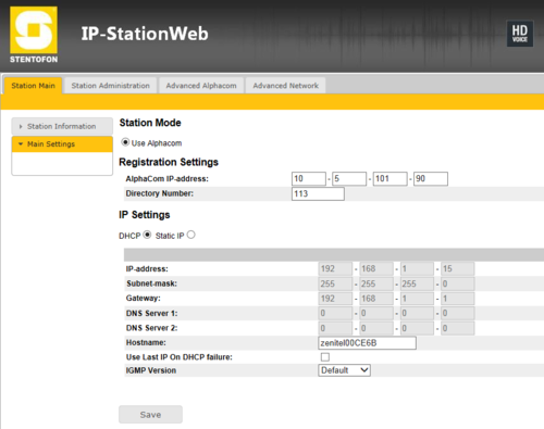
In Station Main -> Main Settings, set the following parameters:
- AlphaCom IP-address: Enter the IP address of the AlphaCom server/exchange in which the IP-ARIO unit is to be registered
- Request Directory Number: Enter the directory number of the IP-ARIO unit
- If a directory number is not entered, the IP-ARIO unit will register with its MAC address. The MAC address is found on the Station Info page and needs to be entered into the AlphaPro programming tool.
Under IP Settings, select one of the following options:
- DHCP – Use this option if the IP-ARIO unit should receive IP Settings from a DHCP server.
- Static IP – Use this option if the IP-ARIO unit should use a fixed IP address. Enter the IP address, subnet mask and gateway address.
- Click Save followed by Apply to apply the new configuration settings.
AlphaPro Settings
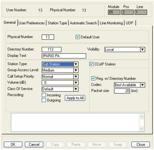
Open the AlphaPro programming tool on your PC and click the Users & Stations icon.
IP-ARIO must be configured as a CCoIP station:
- Enter a Directory Number identical to the directory number entered in the IPARIO unit
- Enter any descriptive Display Text
- For Station Type, select Sub Station
- Check the CCoIP Station box
- Check the Reg. w/ Directory Number box
Configuring PA interface
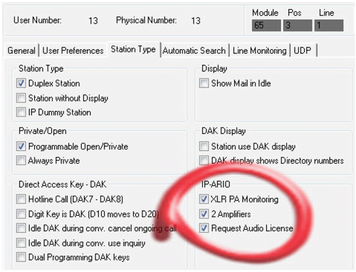
In AlphaPro, Users & Stations, select the IP-ARIO from the list box, and click the Station Type tab. Under IP-ARIO, set the following flags:
- Check the XLR PA Monitoring box
- Check the 2 Amplifiers box
- Check the Request Audio License box
Configuring Mobile Radio Interface
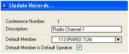
The IP-ARIO unit should be defined as Default Speaker in the Simplex Conference used for radio listening.
- In AlphaPro, click the Simplex Conferences icon.
- Select a Conference and click Change
- Select the IP-ARIO as the Default Member
- Enable Default Member is Default Speaker
In the Users & Stations window, click the Station Type tab. Under IP-ARIO, set the following flag:
- Check the Request Audio License box
See Mobile radio interface (IPARIO) for further details.
Configuring Inputs & Outputs
Remote Control Inputs & Outputs are configured under the Exchange & System menu.
![]()
For Remote Control Inputs:
- Click RCI
- Click Change to set RCI Type to Station
- Enter the IP-ARIO Directory number in the Station Number field
- Enter a Pin Number 1 to 8. Pin 1 is input 1, pin 2 is input 2 etc.
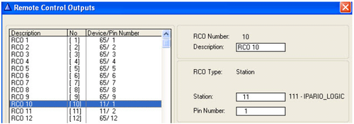
For Remote Control Outputs:
- Click RCO
- Click Change to set RCO Type to Station
- Enter the IP-ARIO Directory number in the Station Number field
- Enter a Pin Number 1 to 8. Pin number 1 is output 1, pin number 2 is output 2 etc.
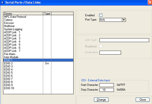
Configuring Remote Serial Port
Click the Exchange & System icon and click Serial Ports.
![]()
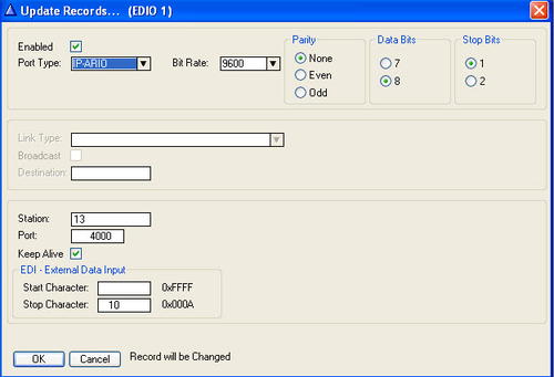
- Select one of the EDIO drivers and click Change
- Check the Enabled box
- Set Port Type to IP-PARIO
- Enter the physical number of the unit in the Station field
- Enter the port number in the Port field
- The port number (e.g. 4000) must be defined and opened under Filters in AlphaWeb
- Click OK

|
|
Local Status Monitoring
The Local Status Monitoring (LSM) feature can be started anytime after booting up the IP-ARIO unit. LSM will show the status on the following monitored items:
- PA 1 and PA 2 for 20 kHz speaker monitoring
- XLR 1 and XLR 2 for XLR connectors connection status
- RCI 1 to RCI 8 showing active or non-active RCI inputs
- RCO 1 to RCO 8 showing active or non-active RCO outputs
LSM is started by using a pin to press the pinhole Reset button located on the front-right of the unit. All LEDs at the front of the unit will be lit as long as the Reset button is pressed (as visual verification of the LED status). When the Reset button is released, LSM continues and the LEDs will show the following:
- CALL LED fast flashing to indicate that the LSM feature is active.
- STATUS LED indicates monitored group (3 groups)
- PA/XLR (green off, red off)
- RCI (green on, red off)
- RCO (green off, red on)
- RADIO LED indicates monitored item within group, mix of LEDs on, off, slow and fast flashing.
- ERROR LED indicates status of monitored item, on if fail or active, off if OK or non-active.
PA/XLR needs approximately 10 seconds to be updated if the status changes, i.e. if the XLR connector is disconnected and then reconnected.
RCI and RCO will show instant updating if the status changes, i.e. if RCI 1 changes status, this will be immediately indicated on the ERROR LED if RCI 1 is monitored.
Each time the Reset button is toggled, the status of the next LSM item is indicated on the ERROR LED.
The LSM can be terminated at any time by pressing and holding the Reset button for at least 2 seconds. LSM will auto-terminate 2 minutes after the last Reset button
activity.
The table below shows the relation between the current status of the monitored item and the different LED indicators.
| Local Status Monitoring | ||||||||
|---|---|---|---|---|---|---|---|---|
| Front LEDs | ||||||||
| CALL | STATUS | RADIO | ERROR | |||||
| Toggle # | Monitored Item | Green | Color | Indication | Color | Indication | Red:ON | Red:OFF |
| 0 | PA 1 | FAST | NONE | OFF | GREEN | ON | Fail | OK |
| 1 | PA 2 | FAST | NONE | OFF | GREEN | SLOW | Fail | OK |
| 2 | XLR 1 | FAST | NONE | OFF | RED | ON | Fail | OK |
| 3 | XLR 2 | FAST | NONE | OFF | RED | SLOW | Fail | OK |
| 4 | RCI 1 | FAST | GREEN | ON | GREEN | ON | Active | Non-ACTIVE |
| 5 | RCI 2 | FAST | GREEN | ON | GREEN | SLOW | Active | Non-ACTIVE |
| 6 | RCI 3 | FAST | GREEN | ON | GREEN | FAST | Active | Non-ACTIVE |
| 7 | RCI 4 | FAST | GREEN | ON | RED | ON | Active | Non-ACTIVE |
| 8 | RCI 5 | FAST | GREEN | ON | RED | SLOW | Active | Non-ACTIVE |
| 9 | RCI 6 | FAST | GREEN | ON | RED | FAST | Active | Non-ACTIVE |
| 10 | RCI 7 | FAST | GREEN | ON | YELLOW | ON | Active | Non-ACTIVE |
| 11 | RCI 8 | FAST | GREEN | ON | YELLOW | SLOW | Active | Non-ACTIVE |
| 12 | RCO 1 | FAST | RED | ON | GREEN | ON | Active | Non-ACTIVE |
| 13 | RCO 2 | FAST | RED | ON | GREEN | SLOW | Active | Non-ACTIVE |
| 14 | RCO 3 | FAST | RED | ON | GREEN | FAST | Active | Non-ACTIVE |
| 15 | RCO 4 | FAST | RED | ON | RED | ON | Active | Non-ACTIVE |
| 16 | RCO 5 | FAST | RED | ON | RED | SLOW | Active | Non-ACTIVE |
| 17 | RCO 6 | FAST | RED | ON | RED | FAST | Active | Non-ACTIVE |
| 18 | RCO 7 | FAST | RED | ON | YELLOW | ON | Active | Non-ACTIVE |
| 19 | RCO 8 | FAST | RED | ON | YELLOW | SLOW | Active | Non-ACTIVE |
SLOW means slow flashing at 500 ms on and 500 ms off.
FAST means fast flashing at 250 ms on and 250 ms off.


