ASLT - AlphaCom Subscriber Line Board: Difference between revisions
From Zenitel Wiki
| Line 70: | Line 70: | ||
The cabling from the AlphaCom server to the intercom station is star wiring principle. Use twisted pair cable. Two pairs of wires are required to each station. The maximum distance depends on the cable diameter: | The cabling from the AlphaCom server to the intercom station is star wiring principle. Use twisted pair cable. Two pairs of wires are required to each station. The maximum distance depends on the cable diameter: | ||
*0.5 mm wires: 1.4 km | *0.5 mm wires (AWG24): 1.4 km | ||
*0.6 mm wires: 2.0 km | *0.6 mm wires (AWG22): 2.0 km | ||
*0.9 mm wires: 4.0 km | *0.9 mm wires (AWG19): 4.0 km | ||
The four wires are called a-,b-, c- and d-wires. a-b-wires are "transmit" and cd-wires are "receive". | The four wires are called a-,b-, c- and d-wires. a-b-wires are "transmit" and cd-wires are "receive". | ||
Latest revision as of 13:52, 17 September 2021
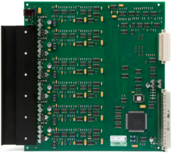
The ASLT line board is used for connection of analog intercom stations to the AlphaCom server.
Highlights
- Each board provides six 4-wire subscriber connections
- 6 RCO remote control outputs (software configurable activation)
- 1 voice-switched conversation per board
- When using handset or full duplex conference unit at both ends, the system is non-blocking within each module
- All subscriber connections suitable for display stations
- Line monitoring
- Software-controlled output volume control
- Hot plug-in/plug-out
- Red/green/amber LED indicates system status
Installation in AlphaCom XE20/XE26

|
|
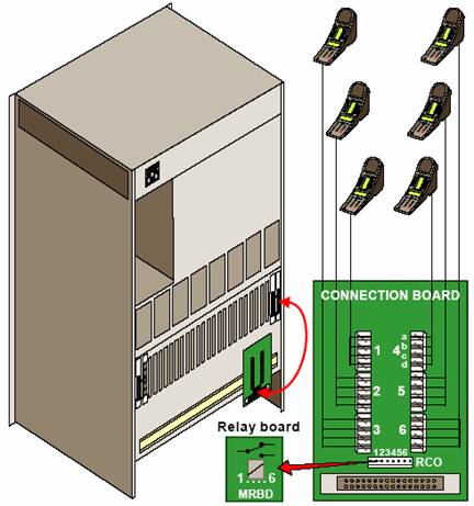
- In the AlphaCom XE26 the ASLT board can be placed in any board position 1-23.
- Board position 1: Physical numbers 1 to 6
- Board position 2: Physical numbers 7 to 12
- !
- !
- Board position 23: Physical numbers 133 to 138
- In the AlphaCom XE20 the ASLT board can be placed in any board position 1 and 8-23.
- Board position 1: Physical numbers 1 to 6
- Board position 8: Physical numbers 43 to 48
- !
- !
- Board position 23: Physical numbers 133 to 138
There are three different subscriber connection methods available:
- Subscriber connection board (1009930200) with 1.5 m connection cables (1009501011) or 3.0 m connection cable. 2 sets of 1009930200 and 1009501011 are included with the XE20 and XE26 exchange packages.
- 5 m (1009501021) and 10 m (1009501023) subscriber connection cables. These cables are un-terminated, color code is packed with the cables.
- Filter and connection card 1009501041 with RJ45 connectors.
Installation in AlphaCom XE7
- In the AlphaCom XE7 the ASLT board can be placed in any board position 1-6.
- Bord position 1: Physical numbers 1 to 6
- Bord position 2: Physical numbers 7 to 12
- !
- !
- Bord position 6: Physical numbers 31 to 36
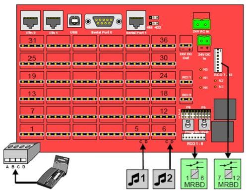
Stations are connected to the AlphaCom XE7 by means of pluggable screw terminals on the backplane.
There are 12 RCO outputs available on pinheaders on the backplane. RCO 1-6 are controlled by the ASLT board in position 1, and RCO 7-12 are controlled by the ASLT board in position 2.

|
Physical numbers 5 and 6 are by default used as inputs for Audio Program distribution, but can alternatively be used for intercom stations. See related article: Physical number 5 and 6 (AlphaCom E7) |
Cabling
The cabling from the AlphaCom server to the intercom station is star wiring principle. Use twisted pair cable. Two pairs of wires are required to each station. The maximum distance depends on the cable diameter:
- 0.5 mm wires (AWG24): 1.4 km
- 0.6 mm wires (AWG22): 2.0 km
- 0.9 mm wires (AWG19): 4.0 km
The four wires are called a-,b-, c- and d-wires. a-b-wires are "transmit" and cd-wires are "receive".
Voltage readings
For troubleshooting it might be useful to check the voltage on the lines with a voltmeter.
Typical voltages across a- and b-wire:
- Open line (no station connected): 32V
- Display station connected: 24-27V
- Non-display station connected: 29-30V
Typical voltages across c- and d-wire:
- Open line, or station connected in Open mode: -21V
- Station connected in Private mode: -19V
- Station in conversation: +9 to +12V


