Vipedia Fault Handling from Operator Stations: Difference between revisions
From Zenitel Wiki
No edit summary |
No edit summary |
||
| (2 intermediate revisions by 2 users not shown) | |||
| Line 1: | Line 1: | ||
{{IL}} | {{IL}} | ||
[[Image:Fault_reporting.png|thumb|500px|Overview]] | [[Image:Fault_reporting.png|thumb|500px|Overview]] | ||
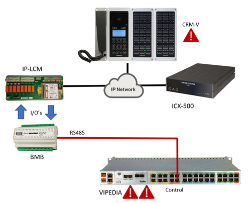
When integrating | When integrating Vipedia PAVA and an ICX-500 system it can be useful to have an indication of the status of the PAVA in the control room. There is no indication of the amount of faults, multiple faults will aggregate into one indication. This article describes how to program this using stations that have DAK buttons with a programmable red LED indication. | ||
Using two relays and two inputs on an [[IP-LCM]] wired to a BMB01 it is possible to do fault indication, fault accept and fault clear on a Vipedia from an operator station. Possible stations are the [[IP Flush Master -V2|IP Flush Master]] or it's [[IP Flush Master DAK-48 Module|DAK-48 Module]] and [[ECPIR-3P]] or it's [[EBMDR-8]]. In this example we will use the 48th button on the DAK-48 panel. | Using two relays and two inputs on an [[IP-LCM]] wired to a BMB01 it is possible to do fault indication, fault accept and fault clear on a Vipedia from an operator station. Possible stations are the [[IP Flush Master -V2|IP Flush Master]] or it's [[IP Flush Master DAK-48 Module|DAK-48 Module]] and [[ECPIR-3P]] or it's [[EBMDR-8]]. In this example we will use the 48th button on the DAK-48 panel. | ||
| Line 14: | Line 14: | ||
==Hardware== | ==Hardware== | ||
The wiring between the Vipedia and IP-LCM is described in the [[Integration with | The wiring between the Vipedia and IP-LCM is described in the [[Integration with Zenitel PAVA using the IP-LCM unit]] article. | ||
The IP-LCM and CRM-V are registered to an ICX-500 | The IP-LCM and CRM-V are registered to an ICX-500 | ||
| Line 140: | Line 140: | ||
}} | }} | ||
[[Category: | [[Category: Zenitel PAVA Integration]] | ||
Latest revision as of 08:38, 28 November 2025
When integrating Vipedia PAVA and an ICX-500 system it can be useful to have an indication of the status of the PAVA in the control room. There is no indication of the amount of faults, multiple faults will aggregate into one indication. This article describes how to program this using stations that have DAK buttons with a programmable red LED indication.
Using two relays and two inputs on an IP-LCM wired to a BMB01 it is possible to do fault indication, fault accept and fault clear on a Vipedia from an operator station. Possible stations are the IP Flush Master or it's DAK-48 Module and ECPIR-3P or it's EBMDR-8. In this example we will use the 48th button on the DAK-48 panel.
The configuration in this article will give the following functionality:
- Blinking red LED on the DAK button for unacknowledged faults
- Pressing the DAK button acknowledges faults
- Steady lit red LED on the DAK button for acknowledged faults
- Dialing a 4 digit code clears the faults. This can only be done on stations with a keypad, so not the ECPIR-3P.
These four functions follow a typical workflow for handling faults.
Hardware
The wiring between the Vipedia and IP-LCM is described in the Integration with Zenitel PAVA using the IP-LCM unit article. The IP-LCM and CRM-V are registered to an ICX-500
Fault indication
On the BMB01 there are two outputs configured. One relay for unacknowledged faults and one for acknowledged faults.
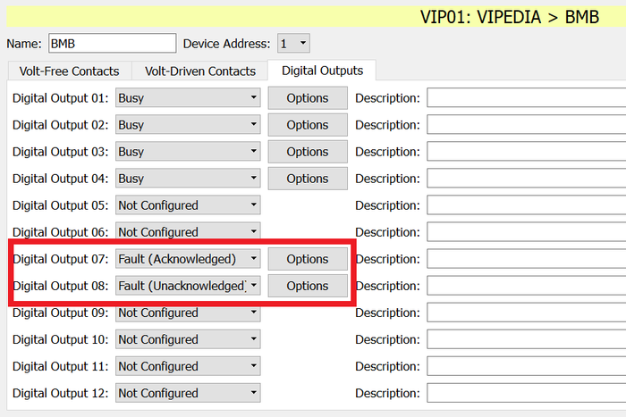 |
| Setting fault outputs |
These two relays are connected to two inputs of the IP-LCM. In the ICX-500 we create an event for each to manipulate the red LED of the DAK button. In this example we use the last button on the DAK 48. The event of for the blinking LED:
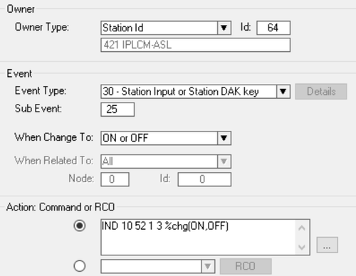 |
| Indicating unacknowledged faults |
Action commands:
IND 10 52 1 3 %chg(ON,OFF)
The event for the steady LED:
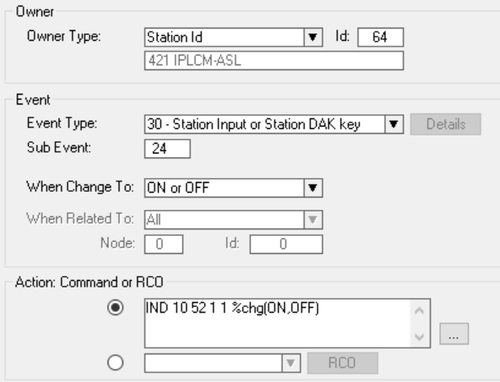 |
| Indicating acknowledged faults |
Action commands:
IND 10 52 1 1 %chg(ON,OFF)
Because the blinking has higher priority over steady lit in the IND command they can be layered in this way.
Fault accept
For accepting the faults we use the same DAK button on the CRM-V and relay 6 of the IP-LCM. This relay is wired into an input of the BMB.
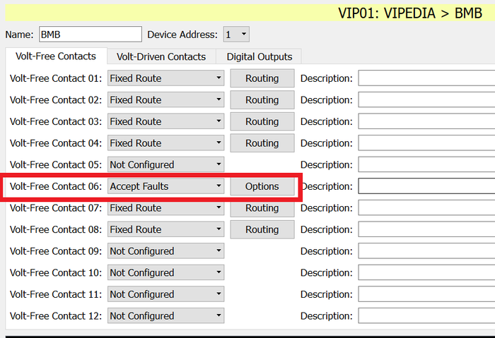 |
| Setting fault accept input |
In the ICX-500 an RCO has to be defined. We use RCO 8 in this example, linked to IP-LCM relay 6. After assigning RCO's the ICX-500 needs a small reset.
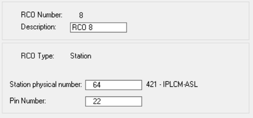 |
| RCO for Relay 6 |
And in an event tied to the DAK button on the CRM-V we pulse the relay for 2,5 seconds.
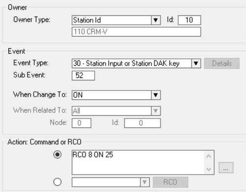 |
| Event for accepting fault |
Action commands:
RCO 8 ON 25
Fault clear
Clearing a fault should of course be protected by a pin number just like on the front panel of the Vipedia. The configuration on the BMB01 is similar to the fault accept. For clearing the faults we use relay 5 of the IP-LCM. This relay is wired into an input of the BMB.
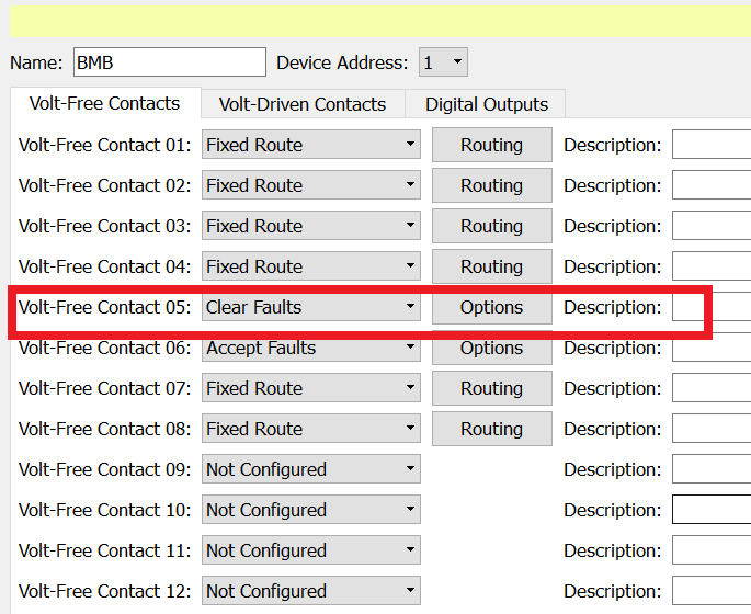 |
| Setting fault clear input |
In the ICX-500 an RCO has to be defined. We use RCO 7 in this example, linked to IP-LCM relay 5. After assigning RCO's the ICX-500 needs a small reset.
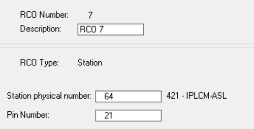 |
| RCO for Relay 5 |
Because we will use a 4 digit code we use an event trigger (feature 85). In the example we created one with number 6506.
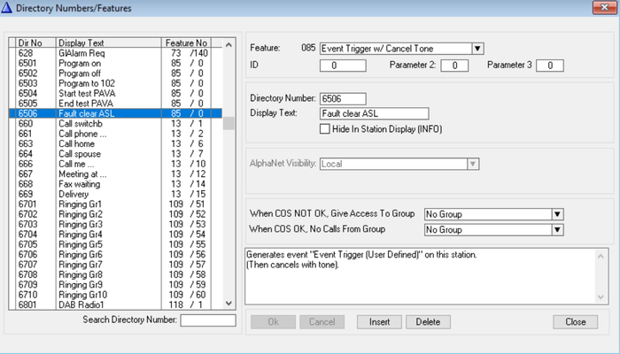 |
| Event trigger feature |
This feature will trigger an event 15 for the CRM-V, which we use to pulse the RCO we defined earlier.
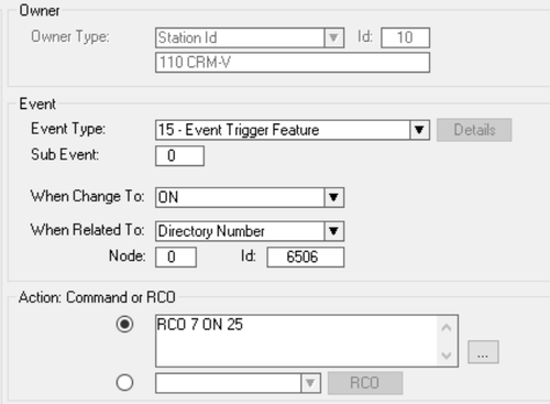 |
| Event for clearing fault |
Action commands:
RCO 7 ON 25

