IP Video Door Station - 1401110200: Difference between revisions
From Zenitel Wiki
No edit summary |
No edit summary |
||
| Line 3: | Line 3: | ||
'''Camera Type: Axis''' | '''Camera Type: Axis''' | ||
==Highlights== | ===<u>Highlights</u>=== | ||
* Robust housing with Aluminium frontplate | * Robust housing with Aluminium frontplate | ||
* IP65 protection to front | * IP65 protection to front | ||
* PoE Powered from one IP network cable | * PoE Powered from one IP network cable | ||
* IP HD Video camera BY AXIS | * IP HD Video camera BY AXIS | ||
* Relay output for remote control, e.g. doors, signal lamps and gates | * Relay output for remote control, e.g. doors, signal lamps and gates | ||
* Button with bi-colour LED ring | * Button with bi-colour LED ring | ||
== | ===<u>[[IP Video Doorstation Connections|InterCom connections]]</u>=== | ||
===<u>Configuration</u>=== | |||
* [[IP Station Configuration]] | |||
* [[CP Cam Configuration]] | |||
===<u>Software upgrade</u>=== | |||
* [[INCA Station Software upgrade|Software Upgrade]] | |||
* CP Cam upgrade | |||
===<u>[[INCA Video Doorstation LED Indicators|LED Indications]]</u>=== | |||
===<u>[[INCA Video Doorstation Board Connectors|Board Connectors]]</u>=== | |||
===<u>[[IP Video Doorstation Dimensions & Mounting Instructions|Dimensions]]</u>=== | |||
===<u>Reset to factory settings</u>=== | |||
*[[INCA Station Restore Factory Defaults|Factory Settings of Audio Module]] | |||
*[[CP-Cam Factory Reset|Factory Settings of Camera Module]] | |||
===<u>[http://www.zenitel.com/product/ip-vandal-resistant-video-station Additional Documentation on Zenitel.com]</u>=== | |||
===<u>Related articles</u>=== | |||
* [[Back box flush mount - 1401199101]] | |||
* [[Back box on wall mount - 1401199111]] | |||
* [[Protection Roof - 1401199121]] | |||
[[Category: INCA Stations]] | |||
==Installation== | ==Installation== | ||
Revision as of 07:40, 26 October 2016
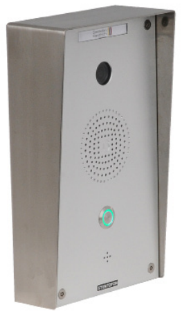
Camera Type: Axis
Highlights
- Robust housing with Aluminium frontplate
- IP65 protection to front
- PoE Powered from one IP network cable
- IP HD Video camera BY AXIS
- Relay output for remote control, e.g. doors, signal lamps and gates
- Button with bi-colour LED ring
InterCom connections
Configuration
Software upgrade
- Software Upgrade
- CP Cam upgrade
LED Indications
Board Connectors
Dimensions
Reset to factory settings
Additional Documentation on Zenitel.com
Related articles
Installation
- Default IP adresses:
- Audio module: 169.254.1.100 (admin/alphaadmin)
- Camera module: 169.254.1.101 (admin/1234)
See article: IP Station Installation
IP Station Configuration
See article: IP Station Configuration
Reset to factory settings
- Factory Settings of Audio Module: IP Station Restore Factory Defaults
- Factory Settings of Camera Module: #Axis Factory Reset
Software Upgrade
See article: INCA Station Software upgrade
Dimensions
See article: IP Stations Dimensions and Mounting Instructions
Related articles
Camera Configuration
Connect to the camera using a webbrowser on default IP address 169.254.1.101.
In the menu that appears, click System Settings, and you will be asked to login:
Username: admin
Password: 1234
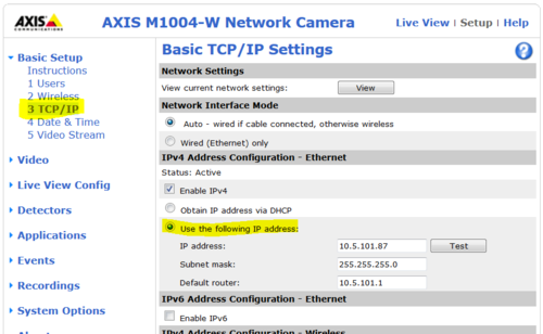
It is recommended to use a static IP address for the camera:
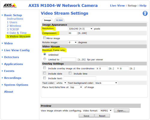
From the Main Menu navigate to Video Stream:
Axis Factory Reset
After a factory default, the Axis camera will get its IP address from a DHCP server.
If there is no DHCP server on the network, it will get the IP address 192.168.0.90.
To restore the factory settings, proceed as follows:
- 1. Disconnect the camera from the power supply and ethernet.
- 2. Remove the four screws securing the rear cover and remove it.
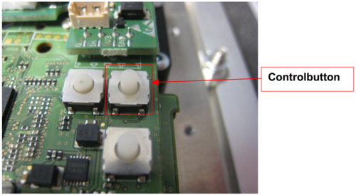
- 3. Keep the Control button pressed while you restore the power supply.
- 4. Hold down the button for about 15 seconds until the status LED is yellow flashing.
- 5. Release the Control Button. The process is complete when the status LEDs light up green.
If no DHCP server is active on your network the new default IP is 192.168.0.90.
The new default user is root with password pass


