Difference between revisions of "ITSV-1 (Edge)"
From Zenitel Wiki
(→Edge Controller configuration) |
(→SIP account) |
||
| Line 38: | Line 38: | ||
# '''SIP Authentication ID''': This ID is identical to the "SIP User ID" | # '''SIP Authentication ID''': This ID is identical to the "SIP User ID" | ||
# '''Name''': This text is shown as Caller ID when placing a call | # '''Name''': This text is shown as Caller ID when placing a call | ||
| − | # Press '''Apply''' to activate the settings | + | # Press '''Save''', then '''Apply''' to activate the settings |
[[File:ITSV-Account2.png|thumb|700px|left|Setting up a SIP account in the ITSV-1]] | [[File:ITSV-Account2.png|thumb|700px|left|Setting up a SIP account in the ITSV-1]] | ||
Revision as of 16:49, 12 March 2019
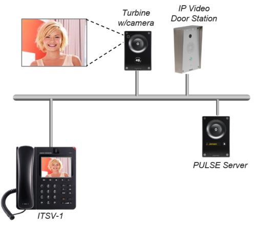
This article describes how to set up the ITSV-1 unit in an IC-EDGE System.
Edge Controller configuration
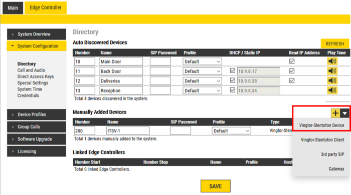
You need to manually add a new account for the ITSV-1. No license is required. When you add a new device, it will automatically be assigned a number and name, which can be modified as required.
- Log on to the Edge Controller
- From the menu Edge Controller > System Configuration > Directory, under the Manually Added Devices section, press the "+" button
- Select 3rd party SIP from the dropdown list
- Modify Number and Name as required
- Optionally one can add a SIP Password. If a password is entered, one have to also manually configure the same password in the ITSV-1 it self. The password is used as authentication during the registration process.
- Press Save to store the new device in the Edge Controller
Configuration of the ITSV-1
Network settings
- Power up the ITSV-1 unit
- Push on the touch screen, and select Settings > About phone > Network status to find the IP address.
- Open a web browser on your computer, enter the IP address into the address bar (e.g. "http://192.168.0.160" or "192.168.0.160") and click Enter.
- Enter the user name (default: admin) and password (default: alphaadmin) in the pop-up dialogue box and click Login
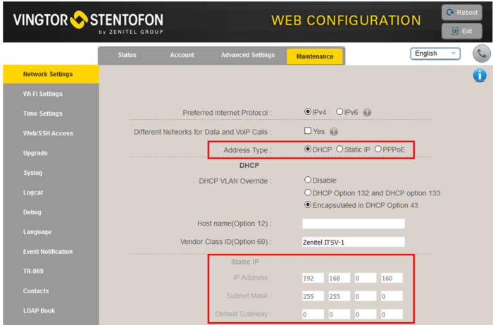
- Select Maintenance > Network Settings to configure the phone to use DHCP (obtain an IP address automatically) or Static IP address.
SIP account
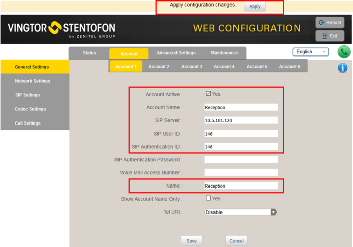
- Select Account > Account 1 > General Settings
- Account active: Check "Yes"
- Account name: Is shown in the LCD screen to identify the account
- SIP Server: Enter the IP address of the Edge Controller
- SIP User ID: Must match the number entered in the Edge Controller
- SIP Authentication ID: This ID is identical to the "SIP User ID"
- Name: This text is shown as Caller ID when placing a call
- Press Save, then Apply to activate the settings
Video Configuration for TCIV
The ITSV intercom can stream video from a TCIV station during a call. By default the ITSV intercom will start video automatically when using H.264 video mode. In case no video is present during a call, navigate to Account > Account 1 > Call Settings, and verify that Start Video Automatically is enabled.
In the TCIV station you need to:
- Log on to the TCIV station
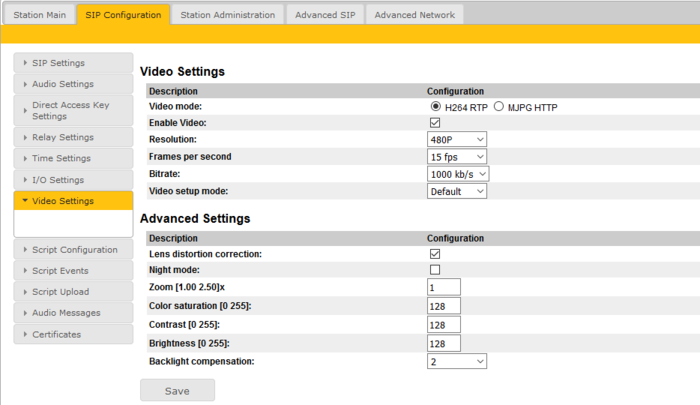
- Navigate to SIP Configuration > Video Settings
- Check Enable Video
- Make sure "Video Mode" = H.264
See Turbine Video Settings for detailed information on each parameter.
Door Opening feature
During conversation with a Turbine or INCA Door Station, the integrated relay of the door station can be operated by pressing digit "6" on the ITSV-1. As the Door Stations by default are configured to trigger on DTMF "6", no additional configuration is required for the Door Opening feature.
If there is a need to restrict which stations should be allowed to do Door Opening, this can be configured via Device Profiles.
Group Call
The ITSV-1 can be configured to receive Group Call audio.
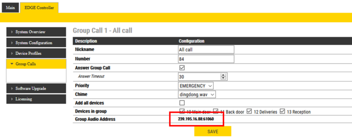
The Edge Controller transmits group call audio using IP multicast technology. Each group call uses its own unique multicast IP address. The multicast IP address can be found by logging on to the Edge Controller, and navigate to Edge Controller > Group Calls.
Make a note of the multicast addresses, then log in to the ITSV-1 station, and navigate to Advanced Settings > Multicast Paging. Set "Multicast Paging Codec" = G722, and enter the multicast address(es) found in the Edge Controller as indicated in the screen shot below:
Press Apply, then Reboot the ITSV station for the new settings to take effect.
When a group call is activated, the ITSV-1 will automatically play the audio in the loudspeaker. The display of the ITSV will show the text of the group call as entered in the "Label" field next to the multicast IP address.
If the ITSV is busy in a regular call when a group call is made, it will by default not play the group call audio. However, if Paging Barge (see screen shot above) is set to value "2" or higher, the current call will be placed On Hold, and the group call audio will be played. When the group call is ended, the ITSV user must press the Hold button to resume the call.
Call Forwarding
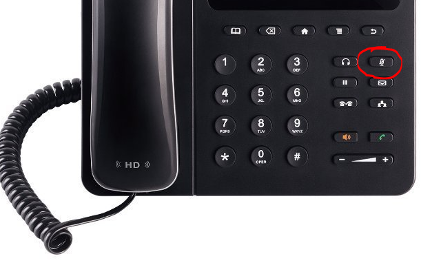
You can toggle Call Forwarding On/Off by means of the DND (Do Not Disturb) button on the phone. When DND is activated there is a red banner across the top of the screen.
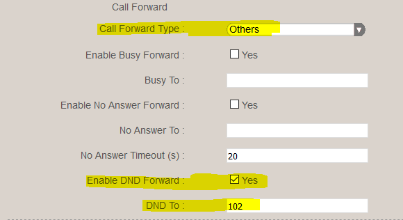
In the Accounts configuration you can activate Call Forwarding when DND (Do Not Disturb) is turned on:
In the same configuration page you can activate Call Forwarding:
- When busy
- When the call is not answered within a preset time
Call Forwarding can also be activated manually from the touch screen. Select: Settings > Personalized Account > [choose account] > Call Forwarding
Video Configuration for IP Video Door Station (1401110100)
The ITSV Video intercom can be configured to show video image from the IP Video Door Station - 1401110100 using MJPEG video format. The cameras should have a static IP address. The ITSV intercom supports up to 30 cameras per account.
The directory number of the Video Door Station must be defined in the Camera List, together with the URL of the camera of the Video Door Station. When a call is received, the phone will look up in this Camera List, and find the correct URL for the associated camera, and ask for the video stream directly from the camera.
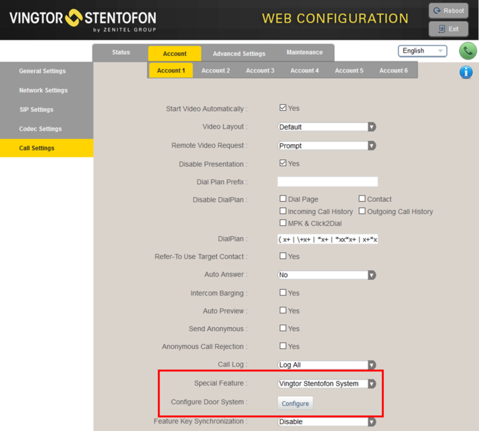
- Select Account > Account 1 > Call Settings
- In "Special Feature", select Vingtor Stentofon Door System
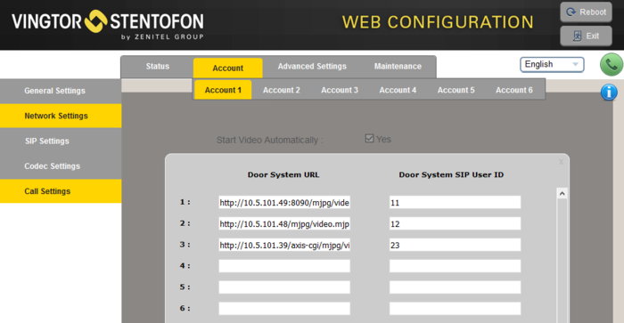
- In "Configure Door System" press the button Configure to open the Camera List
- In the Camera List, enter the camera URL and the directory number of the Video Door station:
URL: http://<IP address of the camera>/mjpg/video.mjpg
- Example: http://10.5.101.48/mjpg/video.mjpg
It is possible to enable basic HTTP authentication for the receiving video stream.
- Example: http://<user>:<pass>@<IP address of the camera>:8090/mjpg/video.mjpg
Configuration of the CP-CAM camera (Station 1401110100)
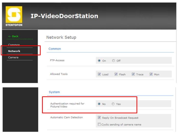
In the camera the authentication for the image/video display has to be deactivated.
- Log on to the CP-CAM camera (default username: admin, password: 1234)
- Select System Settings > Network > System, and change the "Authentication required for Picture/Video" to "No".
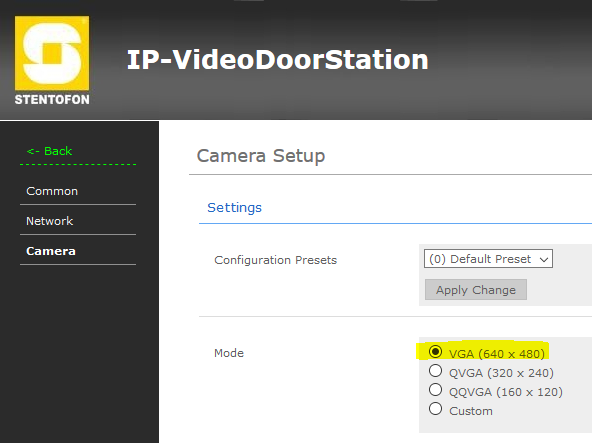
Set the resolution to 640 x 480 pixels:
- Select System Settings > Camera, and set "Mode" to VGA (640 x 480).
Troubleshooting
- To do a network trace on a ITSV-1, see ITSV-1 - Capture Trace
- Not able to call to the ITSV-1 phone from an intercom station. The call is rejected.
- Check the Device Profiles > Outgoing Calls Allowed setting. By default some profiles are not allowed to call other profiles.


