IP Video Door Station - 1401110100: Difference between revisions
From Zenitel Wiki
| Line 91: | Line 91: | ||
'''Camera Name''' - The name of the camera can be set here, which is displayed as header above the video window. The name is also displayed in the password prompt window. <br/> | '''Camera Name''' - The name of the camera can be set here, which is displayed as header above the video window. The name is also displayed in the password prompt window. <br/> | ||
'''Firmware version''' - The installed software version on the CP-CAM is shown here. | '''Firmware version''' - The installed software version on the CP-CAM is shown here. | ||
'''Save Changes''' - Saves the settings permanently and you return to the main menu. | |||
------ | ------ | ||
'''Network Setup''' | '''Network Setup''' | ||
[[File:Cam 7.PNG|thumb|left|500px|Common]] | [[File:Cam 7.PNG|thumb|left|500px|Common]] | ||
<br style="clear:both;" /> | <br style="clear:both;" /> | ||
'''FTP-Access''' - FTP access to the data of the CP-CAM can be turned on here <br/> | |||
'''Allowed Tools''' - Specifies which support program that are allowed to access the CP-CAM <br/> | |||
[[File:Cam 8.PNG|thumb|left|500px|IP-Setup]] | [[File:Cam 8.PNG|thumb|left|500px|IP-Setup]] | ||
<br style="clear:both;" /> | <br style="clear:both;" /> | ||
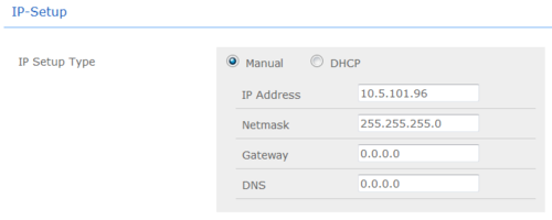
'''IP Setup Type''' <br/> | |||
:Manual/DHCP - Specifies whether the network settings are to be manually or automatically assigned | |||
:IP Address - IP address at which the CP-CAM can be reached on the network | |||
:Netmask - The netmask is entered here | |||
:Gateway - Gateway is entered here | |||
:DNS - DNS server is specified here | |||
[[File:Cam 9.PNG|thumb|left|500px|Hardware]] | [[File:Cam 9.PNG|thumb|left|500px|Hardware]] | ||
<br style="clear:both;" /> | <br style="clear:both;" /> | ||
'''Ethernet Mode''' - Standard settings should always be set to '''Auto'''. The other settings are only for network professional in the event of problems with the automatic <br/> | |||
'''MAC Address''' - MAC address of the camere | |||
[[File:Cam 10.PNG|thumb|left|500px|Ports]] | [[File:Cam 10.PNG|thumb|left|500px|Ports]] | ||
<br style="clear:both;" /> | <br style="clear:both;" /> | ||
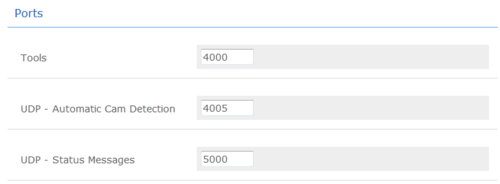
Note! The following port numbers must all have different values, as this can cause malfunction | |||
'''Tools''' - Port for support programs <br/> | |||
'''UDP-Autoomatic Cam Detection''' - UDP port for automatic detection of camera in the network using special software <br/> | |||
'''UDP-Status Messages''' - UDP port for status messages <br/> | |||
[[File:Cam 11.PNG|thumb|left|500px|System]] | [[File:Cam 11.PNG|thumb|left|500px|System]] | ||
<br style="clear:both;" /> | <br style="clear:both;" /> | ||
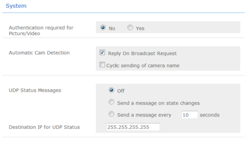
'''Authentication required for picture/video''' - Specifies whether the user requires a password for the video and picture display <br/> | |||
'''Automatic Cam Detection''' - Must be turned on to automatically detect several cameras over the network. Must be turned off after system installation, particularly in network where many broadcasts are sent <br/> | |||
'''UDP Status Messages''' - Settings for status messages <br/> | |||
Off - Camera sends no status messages <br/> | |||
Message after mode change - A message is sent after each mode change. (I/O, camera driver and LED mode) <br/> | |||
Cyclical message - An additional message is sent after a time interval - even if there has been no mode change <br/> | |||
'''Destination IP for UDP Status''' - Destination address of status messages <br/> | |||
[[File:Cam 12.PNG|thumb|left|500px|Save changes]] | [[File:Cam 12.PNG|thumb|left|500px|Save changes]] | ||
<br style="clear:both;" /> | <br style="clear:both;" /> | ||
'''Save Changes''' - Saves the settings permanently and you return to the main menu <br/> | |||
------ | ------ | ||
'''Camera Setup''' <br/> | '''Camera Setup''' <br/> | ||
| Line 115: | Line 138: | ||
[[File:Cam 14.PNG|thumb|left|500px|Configuration Presets]] | [[File:Cam 14.PNG|thumb|left|500px|Configuration Presets]] | ||
<br style="clear:both;" /> | <br style="clear:both;" /> | ||
'''Configuration Presets''' - Here you can select on of several configuration sets of camera settings. | |||
<u>'''Warning!''' All other changes will be lost. Therefore, you should first change the default settings and then the other!</u> | |||
[[File:Cam 15.PNG|thumb|left|500px|Mode]] | [[File:Cam 15.PNG|thumb|left|500px|Mode]] | ||
<br style="clear:both;" /> | <br style="clear:both;" /> | ||
'''Mode''' - Sets the camera resolution <br/> | |||
[[File:Cam 16.PNG|thumb|left|500px|Frames per Second (Sensor)]] | [[File:Cam 16.PNG|thumb|left|500px|Frames per Second (Sensor)]] | ||
<br style="clear:both;" /> | <br style="clear:both;" /> | ||
'''Number of frames per second''' - Defines the number of pictures per second which the video sensor captures. With VGA max 15 (20 at quality 40), by QVGA/QQVGA max 25 <br/> | |||
[[File:Cam 17.PNG|thumb|left|500px|Shown Frames (Video)]] | [[File:Cam 17.PNG|thumb|left|500px|Shown Frames (Video)]] | ||
<br style="clear:both;" /> | <br style="clear:both;" /> | ||
'''Shown Frames''' - Specifies how many of the captured pictures are transmitted as video. Only every X-th picture is sent | |||
[[File:Cam 18.PNG|thumb|left|500px|Zoom]] | [[File:Cam 18.PNG|thumb|left|500px|Zoom]] | ||
<br style="clear:both;" /> | <br style="clear:both;" /> | ||
'''Zoom''' - Setting of the picture enlargement | |||
:Zooming is only possible with a resolution smaller than VGA (640x480). | |||
:The zoom factor can only be as large as the factor which reduced the picture. | |||
:So with QQVGA max 4.0x. | |||
:A value to large is automatically reset to 1.0x. | |||
:Generally: | |||
::(Re''solutionX * Zoom)<u><</u>640'' | |||
::(Re''solutionX * Zoom)<u><</u>480'' | |||
[[File:Cam 19.PNG|thumb|left|500px|Displacement]] | [[File:Cam 19.PNG|thumb|left|500px|Displacement]] | ||
<br style="clear:both;" /> | <br style="clear:both;" /> | ||
'''Displacement on X-Axis/Y-Axis''' - It is possible to adjust a picture (only at resolutions < VGA). To view a certain section of the picture, move the section in the X and Y direction so far until the desired picture is visible. Incorrect values are corrected automatically. <br/> | |||
[[File:Cam 20.PNG|thumb|left|500px|Quality (JPEG compression]] | [[File:Cam 20.PNG|thumb|left|500px|Quality (JPEG compression]] | ||
<br style="clear:both;" /> | <br style="clear:both;" /> | ||
''IR Lighting/Nightvision'' | ''IR Lighting/Nightvision'' | ||
Revision as of 09:57, 7 November 2014
Camera Type: CP-Cam
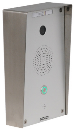
The STENTOFON Vandal Resistant IP Video Station (item 1401110100) is tough, durable and resilient, and designed for use in the harshest of environments. The station is typically used as a communication, information or emergency point and connects directly to the IP network making it easy to deploy – anywhere and at any distance. Designed for CCoIP® the station offers a set of critical communication features such as integrated firewall, group call, call priority and over-ride, to name just a few. This enables you to deliver instant, efficient and secure voice, video and data services in an IP environment.
Installation
See article: IP Station Installation
Station Board Connectors and LED Indications
See article: IP Station Board Connections and Indications
IP Station Configuration
See article: IP Station Configuration
Reset to factory settings
See article: IP Station Restore Factory Defaults
Software Upgrade
See article: IP Station Software upgrade
Dimensions
See article: IP Stations Dimensions and Mounting Instructions
Camera
Connect to the camera using a webbrowser on default IP address 169.254.1.101.
In the menu that appears, click System Settings, and you will be asked to login:
Username: admin
Password: 1234
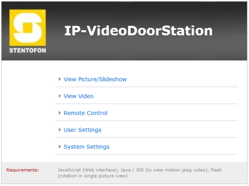
CameraWeb
Main Menu
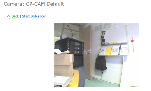
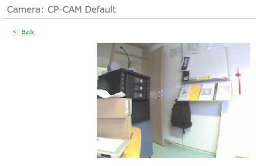
View Picture/Slideshow
This option is used to display single pictures fo the camera.
By clicking Start, the camera starts displaying a picture every second.
With Stop, the current picture is permanently displayed.
With Back, you return to the main menu.
View Video
With this selection, the video images are displayed.
Settings for the displayed video can be found under Settings -> Camera.
With Back, you return to the main menu.
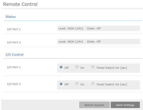
Remote Control
The CP-CAM can, in conjunction with an IO interface, provide two opto-coupler inputs or two relay outputs.
A door opener or light can for example be switched vie the web interface using the outputs.
Status
I/O Port 1 - Shows the status of the first I/O input
I/O Port 2 - Shows the status of the second I/O input
I/O Control
I/O Port 1 - The switching state of the first output can be set here
I/O Port 2 - The switching state of the second output can be set here
Off - Output alway off
On - Output is permanently switched on
Timed Switched On - Here, the output can be set for a given time period
Reboot System - Restarts the CP-CAM
Send Settings - Sends the settings to the camera to be effective
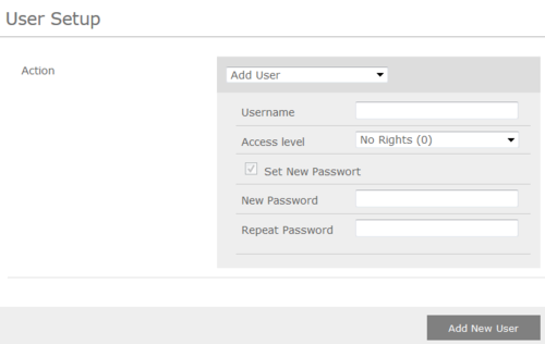
User Setup
In this menu the users of the CP-CAM can be managed. A user can be assigned different permissions.
The availability of the video and picture display without password entry can be set under Settings->Network.
Action - Ability to add, change or detele a user
Username - In this field, user name is entered (no special characters allowed)
Access Level - Selection of authorixzation for a user
- No rights (0) - User is deactivated
- Viewer (2) - User has access to single picture and video display, as well as for the camera ID
- Remote Control (4) - User has additionally access to remote control
- Administration (8) - User has unrestricted access
Set New Password - Enter password
Repeat Password - Confirm password
Add New User/Change/Delete - By clicking on this button, the settings are applied
With Back, you return to the main menu
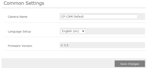
Common Settings
Camera Name - The name of the camera can be set here, which is displayed as header above the video window. The name is also displayed in the password prompt window.
Firmware version - The installed software version on the CP-CAM is shown here.
Save Changes - Saves the settings permanently and you return to the main menu.
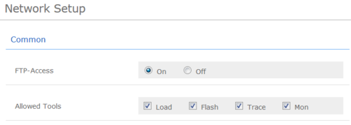
Network Setup
FTP-Access - FTP access to the data of the CP-CAM can be turned on here
Allowed Tools - Specifies which support program that are allowed to access the CP-CAM
IP Setup Type
- Manual/DHCP - Specifies whether the network settings are to be manually or automatically assigned
- IP Address - IP address at which the CP-CAM can be reached on the network
- Netmask - The netmask is entered here
- Gateway - Gateway is entered here
- DNS - DNS server is specified here
Ethernet Mode - Standard settings should always be set to Auto. The other settings are only for network professional in the event of problems with the automatic
MAC Address - MAC address of the camere
Note! The following port numbers must all have different values, as this can cause malfunction
Tools - Port for support programs
UDP-Autoomatic Cam Detection - UDP port for automatic detection of camera in the network using special software
UDP-Status Messages - UDP port for status messages
Authentication required for picture/video - Specifies whether the user requires a password for the video and picture display
Automatic Cam Detection - Must be turned on to automatically detect several cameras over the network. Must be turned off after system installation, particularly in network where many broadcasts are sent
UDP Status Messages - Settings for status messages
Off - Camera sends no status messages
Message after mode change - A message is sent after each mode change. (I/O, camera driver and LED mode)
Cyclical message - An additional message is sent after a time interval - even if there has been no mode change
Destination IP for UDP Status - Destination address of status messages
Save Changes - Saves the settings permanently and you return to the main menu
Camera Setup
Settings
Configuration Presets - Here you can select on of several configuration sets of camera settings.
Warning! All other changes will be lost. Therefore, you should first change the default settings and then the other!
Mode - Sets the camera resolution
Number of frames per second - Defines the number of pictures per second which the video sensor captures. With VGA max 15 (20 at quality 40), by QVGA/QQVGA max 25
Shown Frames - Specifies how many of the captured pictures are transmitted as video. Only every X-th picture is sent
Zoom - Setting of the picture enlargement
- Zooming is only possible with a resolution smaller than VGA (640x480).
- The zoom factor can only be as large as the factor which reduced the picture.
- So with QQVGA max 4.0x.
- A value to large is automatically reset to 1.0x.
- Generally:
- (ResolutionX * Zoom)<640
- (ResolutionX * Zoom)<480
Displacement on X-Axis/Y-Axis - It is possible to adjust a picture (only at resolutions < VGA). To view a certain section of the picture, move the section in the X and Y direction so far until the desired picture is visible. Incorrect values are corrected automatically.
IR Lighting/Nightvision
Video
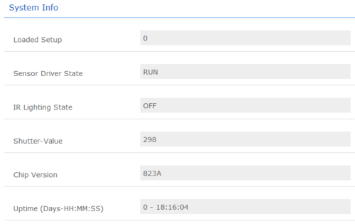
System Info
Compability
This table shows the camera specific settings that must be set depending on the receiver
| Receiving unit | Resolution | Shown Frames | Quality (JPEG compression) | Other2 | Comments |
| IP Video Desktop | 320x240 | Every frame | 100 | xx | yy |
| CP-Cam viewer | xx | xx | xx | xx | yy |
| Cisco xxx | xx | xx | xx | xx | yy |
| SNOM IP Phone | xx | xx | xx | xx | yy |
| Grandstream xxx | xx | xx | xx | xx | yy |
| PhonerLite SIP Client | 640x480 | Every frame | 70 | xx | yy |
| DIVUS Videophone | 320x240 | Every frame | 100 | xx | yy |
These units have been tested and found to be not supported:
- BRIA (CounterPath) SIP client
CP-Cam Factory Reset
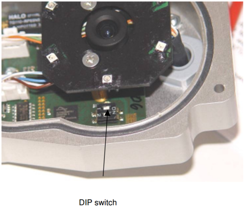
This should be carried out only by experienced technicians. The customer is liable for damages caused by improper opening of the housing.
If the entered IP address is unknown, it is possible to reset the address to 169.254.1.101 using the DIP switch. To proceed, the unit must be opened.
Note: A change of the IP address is made via the web interface of the CP-CAM.
The procedure is as follows:
- 1. Open the CP-CAM so the two DIP switches are accessible ( see picture ).
- 2. Note the switch position and then turn both switches to „OFF“.
- 3. Connect PC with the IP number range 169.254.1.xxx and set the desired IP address in the web interface.
- 4. Turn switch positions back to original positions.
- 5. Close housing properly.

