Configuration guide for IP Heavy Duty v2
From Zenitel Wiki
This article is applicable for IP Heavy Duty Stations used in ICX-AlphaCom mode.
AlphaPro Configuration
Hotline Call
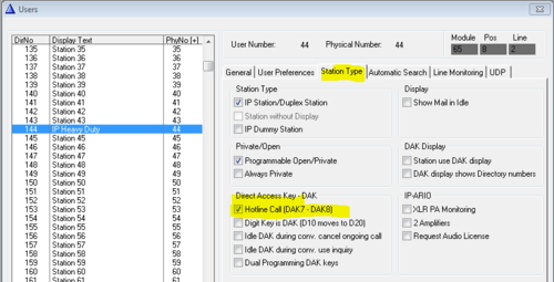
Enable the hotline function by selecting the hotline station in the listbox in Users & Stations, select the Station Type tab, and check the Hotline flagg:
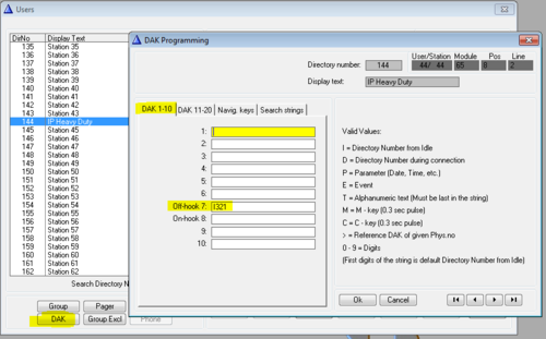
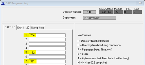
In Users & Stations, select the DAK button, and enter the call destination on DAK 7:
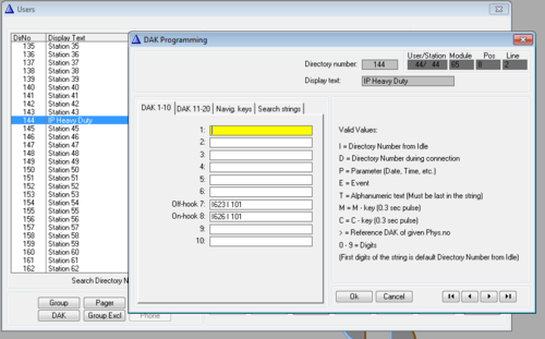
If the hotline call should generate a call to a Ringing Group instead, enter "I 6701" on DAK 7. If the call should be cleared when replacing the handset, enter "C" on DAK 8, else leave DAK 8 blank.
Hotline Call Delay
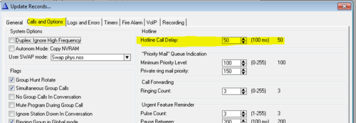
By default there is a 5.0 second delay from the handset is lifted until the call is placed. Often you want the call to be placed immediately. To change the delay time, select Exchange & System, System, Calls and Options.
Direct Access Keys D1 to D3
The Full Keypad models have three Direct Access Keys, D1 to D3, which will trigger DAK key 1, 3 & 5 in the ICX-AlphaCom.
Additional Call Indication (optional)
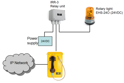
The built-in relay in the IP Heavy Duty telephone can be used to operate an additional call indication device, such as a rotary light.
Additional equipment required:
- Rotary light 24VDC (Item 300 6102 041)
- IRR-3 relay box (Item 102 0600 992)
- 24VDC power supply (Minimum 3A)
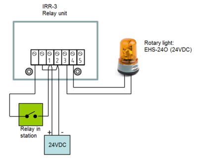
Connection diagram:
Configuration
The built-in relays in the IP Heavy Duty telephone is controlled by the RCO command in the event handler.
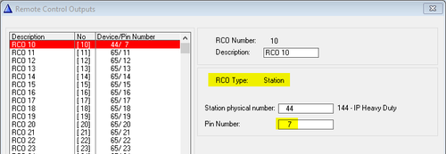
To map the relays of the IP Station to logical RCO's, select Exchange & System -> RCO. Pick a free RCO, select Change and set the RCO Type = Station, enter the physical number of the IP Station, and set pin number = 7 (8 for the second relay).
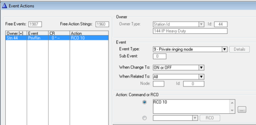
In Users & Stations, select the IP Heavy Duty telephone from the list box, then press Events, and Insert a new event with the following properties. This will cause the relay to operate during the ringing of an incoming call.
Note: The internal ringer device is not in use. The reason is that the housing of the IP telephones are also used in analog versions of the telephone, connected to regular 2-wire telephones lines. Then the ringer is operated by the ringing voltage from the telephone exchange. Although the ringer device is not in use in the IP Heavy Duty station, it has not been removed as it would jeopardize the IP rating of the station.


