Configuration guide for IP Heavy Duty
From Zenitel Wiki
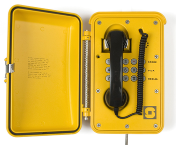
This article pertains to the following STENTOFON IP Heavy Duty Stations:
- 1008072100 - IP Heavy Duty Station, Full Keypad
- 1008072120 - IP Heavy Duty Station, No Keys
- 1008072200 - Ip Heavy Duty Station with door, Full Keypad
- 1008072220 - IP Heavy Duty Station with door, No Keys
Installation
The table below is an overview of the main connectors involved when installing the IP Heavy Duty Station.
Note! To access these connectors the frontplate must be removed
| LAN (P1) | 10/100 Mbps RJ45 port for LAN (uplink) connection. Supports PoE (802.3af). Draws power from either spare line or signal line. |
| AUX (P2) | 10/100 Mbps RJ45 port for auxilliary equipment such as PC or IP Camera. |
| Input/Output | Pluggable screw terminal |
| Local Power | Pluggable screw terminal, 17-27 VDC Idle 4W, max. 8W |
Power Supply
The IP Heavy Duty Station supports Power over Ethernet (PoE, IEEE 802.3 a-f) where power can be drawn from either the spare line or signal line. If PoE is not available, the IP Heavy Duty Station can be connected to a local power. A 24 VDC power supply should be then used.
Connections
There are four connectors on the IP Station circuitboard, P1-P4:
- P1 RJ45 LAN port is for connecting to the network and the AlphaCom Audio Server.
- P2 RJ45 AUX port is for connecting to auxiliary equipment such as a PC.
- P3 6-pin pluggable screw terminal for external connections:
- Pin 1/2: Connection of external 8 ohm loudspeaker (optional)
- Pin 3/4: Internal NO relay contact for additional call indication etc.
- Pin 5/6: Connect 24VDC for station if PoE is not used.
- P4 6-pin pluggable screw terminal for internal connections.
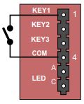
- Pin 1/4: Input for PTT from headset and for restoring Factory Default Setting
- Pin 2/4: Call button no.2 or logical input (optional)
- Pin 3/4: Connected to hookswitch (reed-switch)
- Pin 5/6: Station LED for call and message info. (Pin 6 is positive.)
- TP1/2 Audio output to handset speaker (0dBm 600ohm balanced)
WEB Configuration
The IP Heavy Duty Station features an embedded web server, which allows users to log in via a standard web browser.
At commissioning, the IP Station needs to be configured to make it possible for the IP Station to subscribe to an AlphaCom Audio Server.
Connect both the PC and the IP Station to a PoE switch.
The factory default IP address of the Station is 169.254.1.100. In order for your PC to communicate with the Station it is necessary to change its Internet Protocol Properties to use an IP address that is in the same range as 169.254.1.100, e.g. 169.254.1.1 with subnet mask 255.255.0.0.
After the IP properties have been changed, access the Station by logging into the web interface using a standard web browser:
1. Open a web browser.
2. In the browser’s Address bar, type 169.254.1.100 and press the ENTER key
- The Station Login page is displayed:
To log in to the Station:
1. Click Unsecure Login (HTTP)
2. Enter the default User name: admin
3. Enter the default Password: alphaadmin
The Station Information page will now be displayed, showing the IP Station Configuration.
Use the menu bar at the top and the menus at the left to browse through the different pages.
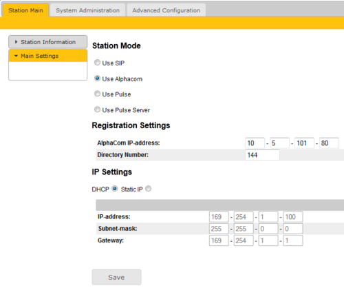
Main Settings
- Click Main Settings under Station Main to access the page for configuring IP parameters.
Station Mode
- Select Use AlphaCom
Registration Settings
- Enter the IP address of the AlphaCom Audio Server in which the IP Station is to be a subscriber in the AlphaCom IP-address field.
- Enter the directory number of the telephone in the Directory Number field.
- If a directory number is not entered, the Station will register with its MAC address. The MAC address is found on the Station Information page and needs to be entered into the AlphaPro programming tool.
IP Settings
- DHCP Use this option if the IP Station should receive the IP settings from a DHCP server.
- Static IP Use this option if the IP Station should use a static IP address. Enter the IP address, subnet mask and gateway address.
- Click Save followed by Apply to apply the new configuration settings.
Keyboard configuration
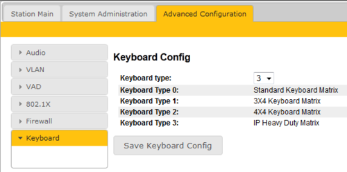
On IP Heavy Duty telephones with full keypad the keyboard configuration needs to be set. This is done via the Station web server:
1. Navigate to the Advanced Configuration tab.
2. Select Keyboard from the menu on the left.
3. Select Keyboard Type 3
4. Press “Save Keyboard Config”
External loudspeaker (optional)
An external 8 ohm loudspeaker must be connected if ringing signal and announcements are to be received. The loudspeaker is connected to pin1 and 2 (LS) on connector P3. To disable audio in the external speaker when the handset is lifted, the following configuration must be made. In the Station web navigate to Advanced Configuration -> Audio and enable the Override Amplifier checkbox.
Note the internal ringer device is not in use. The reason is that the housing of the IP telephones are also used in analog versions of the telephone, connected to regular 2-wire telephones lines. Then the ringer is operated by the ringing voltage from the telephone exchange. Although the ringer device is not in use in the IP Heavy Duty station, it has not been removed as it would jeopardize the IP rating of the station.
AlphaPro Configuration
Hookswitch
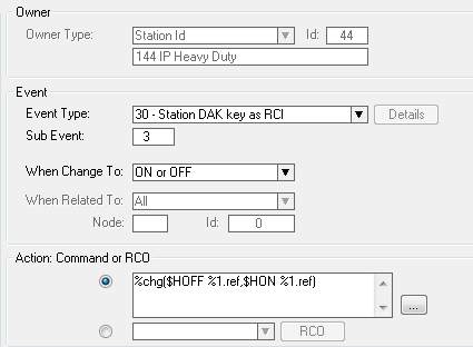
The handset hook-switch is connected between Key3 and Common on terminal block P4 on the IP Station Board (Input 3). An event must be created that reports correct handset status to the AlphaCom. In Users & Stations, select the Events button, press Insert and enter an event with the following properties:
The action string is: %chg($HOFF %1.ref,$HON %1.ref)
Hotline Call
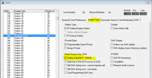
Enable the hotline function by selecting the hotline station in the listbox in Users & Stations, select the Station Type tab, and check the Hotline flagg:
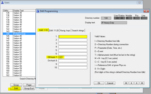
In Users & Stations, select the DAK button, and enter the call destination on DAK 7:
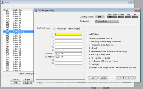
If the hotline call should generate a Call Request instead, enter "I 623 I xxx" on DAK 7, where xxx is the target station. If the Call Request should be cleared when replacing the handset, enter "I626 I xxx" on DAK 8, else leave DAK 8 blank.
Hotline Call Delay
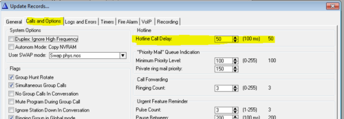
By default there is a 5.0 second delay from the handset is lifted until the call is placed. Often you want the call to be placed immediately. To change the delay time, select Exchange & System, System, Calls and Options.
Additional Call Indication (optional)
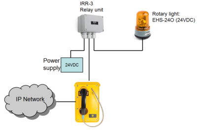
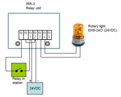
The built-in relay in the IP Heavy Duty telephone can be used to operate an additional call indication device, such as a rotary light.
Additional equipment required:
- Rotary light 24VDC (Item 300 6102 041)
- IRR-3 relay box (Item 102 0600 992)
- 24VDC power supply (Minimum 3A)
Connection diagram:
Configuration
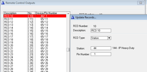
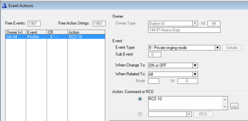
The built-in relay in the IP Heavy Duty telephone is controlled by the RCO command in the event handler.
To map the relay of the IP Station to a logical RCO, select Exchange & System -> RCO. Pick a free RCO, select Change and set the RCO Type = Station, enter the physical number of the IP Station, and set pin number = 1.
In Users & Stations, select the IP Heavy Duty telephone from the list box, then press Events, and Insert a new event with the following properties. This will cause the relay to operate during the ringing of an incoming call.
Troubleshooting
Indication LED's
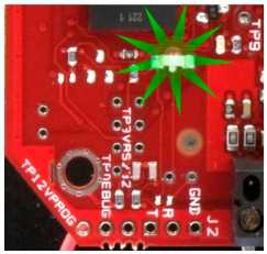
On board status indication LED
- Blinking 2 red + 1 green: Station does not have connection to the AlphaCom XE exchange
- Blinking 1 red + 2 green: Station has connection to AlphaCom XE exchange, but has not been registered
- Blinking 3 green: Station connected and registered in the AlphaCom XE exchange
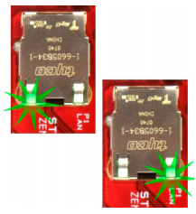
LAN LEDs on RJ45-sockets
- Left LED:
- Steady light Ethernet connection OK
- Blinking Ethernet traffic
- No light No Ethernet connection
- Right LED:
- Light 100 Mbit Ethernet connection
- Light 10 Mbit Ethernet connection
Restore Factory Default Settings
It may be desired to reset an IP Heavy Duty telephone to its original settings if, for instance, the password for the web server is forgotten.
The telephone can be set to use either Static IP or DHCP.
- On the rear side of the PCB there is a red status LED. You cannot see the actual LED, but you can se the red light from it. Pay attention to this LED during the procedure
- Connect a push button (KEY1) between pin 1 and 4 on the P4 connector.
- Press the button, and power up the telephone
- Keep the button pressed. Release the call button after exactly 2 blinks of the LED
- Let the LED blink for exactly 2 (Static IP) or 4 times (DHCP), then press the button again
- Keep the button pressed until it confirms successful factory reset by 2 (Static IP) or 4 (DHCP) fast blinks of the LED
Factory default values:
- Station mode: Pulse
- Station IP address: 169.254.1.100
- Username: admin
- Password: alphaadmin

